Technical introduction to data fiber
The subject of optical data networks is very complex, and no single source (not even an encyclopedic tome
of several thousand pages) can cover it exhaustively. On this page, I summarize the principal choices of
hardware one is likely to make in the context of integrating optical network equipment into a home or
small-business network. During the past two decades, it has become commonplace for an ISP to deliver Internet access to homes and small businesses via optical fiber direct to the real estate. Typically, a mains-powered media converter is mounted on a wall at the point where the fiber enters the building, and from this point to the router the data connection is typically via a 1 GGbps, Gigabit per second Ethernet link using a copper cable as physical medium. The data connection from the router to the client devices via a LAN is often through WiFi in homes and small businesses, unless the premises are wired with copper Ethernet cables. In principle, an ordinary optical fiber of a type commonly used by an ISP can carry data traffic at up to 10 G or more. In practice, the traffic speed is capped to a much lower throughput by the ISP subscription. 100 MbpsMegabit per second is a typical maximum download speed for a low-cost subscription. Upload speeds can be even lower, but unless you are running an Internet server or need to make frequent uploads of large amounts of data, this is unlikely to be a practical problem. Copper Ethernet cable with RJ45 connectors can carry up to 10 G if the wiring is properly done with reasonably modern cable. For short distances, even older Ethernet cable not certified for 10 G may work satisfactorily at this speed. The fastest commonly used current WiFi versions are 6 and 6E. WiFi 6 in practical situations is capped at 1 G even under optimal conditions. 6E in practice reaches around 1.5 G. Both are starkly limited by walls and other physical obstacles. If a reliable 1 G throughput is desired in a multi-room LAN, multiple Wi-Fi APsaccess points, either wired to 1G Ethernet or working in a mesh configuration, must be used. Wi-Fi also carries the added cost that all Wi-Fi devices that need a high throughput must be capable of using the same Wi-Fi version. The obvious advantage of a Wi-Fi mesh is that, once the optimal placements for APs and their powering and interconnections are implemented, no wired network connections are necessary for the network clients. On the other hand, copper Ethernet cabling is very reliable, but constrained by the placement of network outlets. This is especially true in home environments where the wiring conduits run inside walls, but less so in office environments equipped with panel-covered false ceilings that make re-wiring much easier. Cost-wise, copper Ethernet and the associated Ethernet switches remain the cheapest medium. 1 G RJ45 Ethernet electronics are cheap, and by far the most common built-in wired network interfaces in stationary devices. Nowadays, few network-enabled devices are designed with old 100 Mbps "fast Ethernet" connections, and the economic savings afforded by a 100 Mbps RJ45 interface over a 1 G RJ45 interface are minimal. 1 G RJ45 interfaces do not use much energy and generate only a small amount of heat. Several modern PC motherboards are equipped with a built-in 2.5 G RJ45 interface. This interface generates significantly more heat than a 1 G RJ45, but a small heatsink or the 5-10 cm2 surface of a hybrid module are sufficient to dissipate it. On the other hand, at present a 10 G RJ45 interface generates several times more heat (both in the interface logic and in the OSI layer 1 driver circuits) and needs a significantly large heatsink and typically also fan cooling. Ethernet routers and switches equipped with multiple 10 G RJ45 interfaces are available, albeit often priced at a premium level that does not reflect their actual production costs. This will likely change in the near future, but at present converting a copper-wired Ethernet LAN from 1 G to 10 G requires a significant investment. There is, however, a gradual upgrade path that does not force the upgrade to be performed on the whole LAN at the same time (see below). In the following discussion, I use text highlighted in green, like this paragraph, to summarize the principles and main suggestions that emerge from the present discussion. These suggestions do not necessarily apply to all contexts, but nonetheless they are the product of my experience so far. I use text highlighted in red, instead, to indicate possible pitfalls and things to avoid. GBIC, SFP, or SFP+?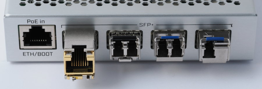
During the past decade, the use of optical fiber, once generally restricted to ISP connections, WANs and telecom, has become more and more common in LANs, campus networks and MANmedium area networks. This is due to a strong reduction in price of the optical media and transceivers, the broader availability and lower prices of LAN routers and switches that can use optical transceivers, and the fast increasing needs for very high data throughput within LANs. While 1 G was once regarded as sufficient for a LAN client, multi-Gbps LAN connections are more and more often regarded as a necessity. Other factors that promoted the widespread adoption of optical fiber media in LANs are the shrinking size and power requirements of the transceivers used in optical networks. The GBICgigabit interface converter transceivers used in the past are relatively large, designed to plug into a metal cage with an opening of approximately 10 by 30 mm, and their housings and/or cages are often covered in cooling fins. At present, GBIC transceivers have virtually disappeared, replaced by SFPsmall form-factor pluggable (normally up to 1 G, although the technology supports up to 4 G) and the externally identical SFP+enhanced small form-factor pluggable (up to 10 to 50 G) requiring a cage opening of 8.5 by 13.4 mm, which is just a little less than an RJ45 plug. This makes SFP/SFP+ cages as space-saving as RJ45 sockets on the panels of network equipment. Avoid the installation of new equipment that uses GBIC transceivers. Quite simply, GBIC makes no sense anymore. 10 G SFP+ cages are commonplace, and network devices equipped with these cages relatively affordable. SFP28 (25 G) and faster cages physically compatible with SFP are today restricted to equipment used by ISPs, large corporate servers and their network infrastructure, or other special purposes. Other types of transceiver cages capable of even larger throughput and using transceivers of different physical formats, like QSFPquad SFP, are found mainly in WAN network devices. The depth of SFP and SFP+ cages (48.8 mm) is of course greater than RJ45 receptacles, and the front of most optical transceivers projects roughly 8-10 mm out of the cage. Transceivers equipped with an RJ45 receptacle need to project roughly 20 mm out of the cage. SFP/SFP+ cages can be ganged together at a distance of less than 1 mm between adjacent cages, and in this way allow roughly the same number of receptacles as RJ45 receptacles on the front panel of large switches. However, using individual cages and leaving a distance of a few mm between adjacent cages, as done in the device shown in Figure 1, improves air circulation and cooling, and allows the use of 10 G optical transceivers in fanless network equipment. SFP/SFP+ transceivers lock in place when fully inserted into a cage. To extract a transceiver, it is necessary to disconnect its cable(s), then pull down and outward a wire handle mounted at the front of the transceiver by 90°, and finally pull the transceiver out of the cage by gripping this handle. The top of the handle often carries a color-coded insert that indicates the wavelength emitted by the transceiver. At present, the best upgrade path to an optical LAN is to choose routers and switches equipped with SFP+ cages, possibly combined with a number of built-in 1 G RJ45 Ethernet interfaces to allow the continued use of legacy network devices. The needed number of SFP+ cages depends on the number of devices that are expected to need a 2.5 G to 10 G connection in the future, or that are located too far from the switch/router to use copper cable. While waiting for the LAN clients to be upgraded to a higher throughput, the cages can be populated with 1 G RJ45 transceivers, which are cheap and allow the continued use of present network clients and wiring. SFP cages are in most cases limited to 1 G. Therefore, a router or switch equipped with SFP cages allows no future improvement in throughput, compared to a device with built-in 1G RJ45 ports. Therefore, my recommendation is to avoid purchasing new routers and switches equipped only with SFP cages (as opposed to SFP+). I do not recommend the use of 10 G SFP+ RJ45 transceivers, because they generate large amounts of heat and, in practice, always require fan cooling. It is better to wait a little longer, and then install 10 G optical transceivers (which can operate without fans) and optical cabling in both network devices and network clients. In client computers, this usually requires the installation of a network card equipped with an SFP+ cage (e.g. the Asus XG C100-F), since PC motherboards with built-in SFP+ cages are still rare. The miniaturization trend has also extended to the plugs and sockets of optical fiber cables. For reasons discussed below, some types of optical transceivers must carry two fiber sockets. The sockets of the SCsubscriber/ square/ standard connector optical connectors used in GBIC transceivers have a roughly 7.3 by 8.9 mm receptacle opening, while SFP/SFP+ transceivers have LCLucent/little/local connector sockets with a roughly 4.2 by 4.5 mm opening (not counting the indentation for the latch). As seen in the three rightmost transceivers in Figure 1, this small size is more than enough for a pair of LC sockets on the face of an SFP transceiver. The figure also shows the much larger external bulk of RJ45 transceivers, compared with optical ones. The small (1.249 mm diameter) off-white cylinder that projects from the end of LC connectors is a ceramic ferrules that hold the ends of the optical fiber. Keep your fingers well away from the ferrule. Don't let the ferrule touch anything except an LC receptacle. LC cables, transceivers and connectors always come with plastic plugs that protect the ferrule and the LC receptacle. Remove these plugs only when you are ready to plug the cable into its intended receptacle. Save the plugs and put them back as soon as you unplug an LC cable. At the bottom left of Figure 2 are a few examples of protective covers used to plug the transceiver's receptacle (the black rubber ones), the ferrule of the plug (the small white and small green ones) and the receptacle of the couplers used to join two cables together (the larger white one). The last type of plug often does not make a tight seal in the receptacle. Don't use it for transceivers. Just to be on the safe side, you may decide to blow-clean the covers with a rubber bulb (not with your mouth!) before using them, since they can transport dust deep into a transceiver. Keeping optical plugs and receptacles clean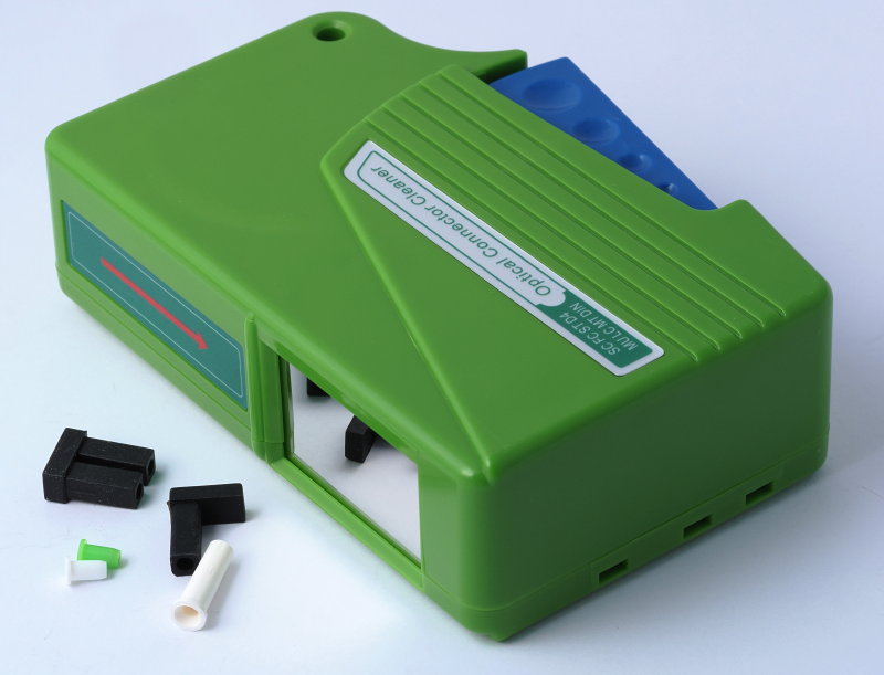
If you plan to do more work with LC cables and transceivers than just plugging a couple of cables into transceivers, you will do well to get one of the cleaning tools used to clean the end of a ferrule (Figure 2). Prices of this and similar tools are ludicrously variable. I have seen some advertised by retailers of optical network equipment at around 1,000 €/US$. The very same tool sells for 20 €/US$ on Amazon, including shipment, and the contained tape is good for hundreds of cleaning cycles. A rubber bulb can be used to blow the plug ferrule and the receptacle of a transceiver clean of dust, before plugging in the cable (don't blow them clean with your mouth!). Some rubber bulb blowers are equipped with a brush at the blower tip's end. Don't use the brush, and preferably avoid this type of blower altogether. The brush fibers quickly become a dust trap. Choose a rather large blower that sits comfortably in your hand, squeezes out a good amount of air, and is equipped with a 5-8 cm long, narrow nylon or teflon (not metal) tip. 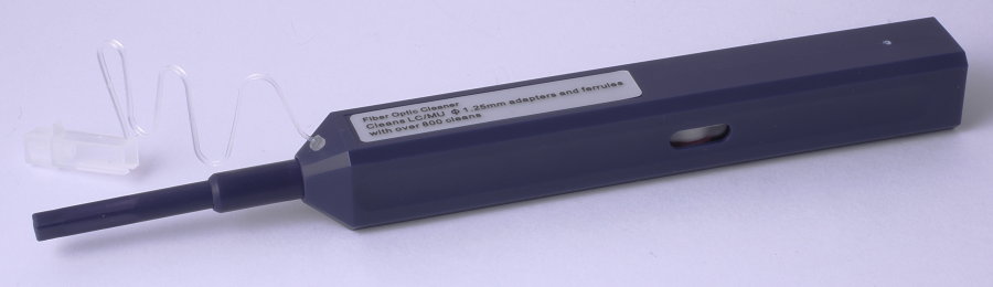
There are also pen-shaped tools designed for cleaning the end of the ferrule contained in a transceiver. If you want to be prepared, you can buy one of these tools (between 15 and 25 €/US$ on Amazon, but also in this case ludicrously high prices for the very same tools abound). Unlike the plug ferrule, the transceiver's ferrule is deeply recessed and I never found it necessary to clean it. This type of cleaning tool does not last for as many cleaning cycles and the one described above, but is likely to become useful only if you happen to plug into a transceiver a cable with an exceedingly dirty ferrule, or if you leave the transceiver's receptacle open in a dusty environment. SFP and SFP+ transceivers in practice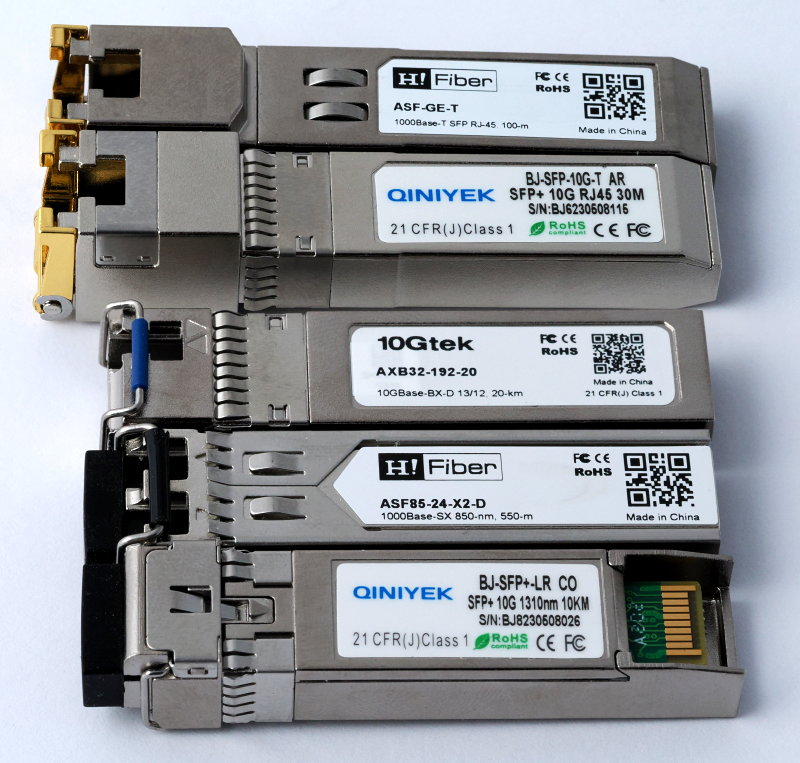
Nowadays, both SFP and SFP+ transceivers (Figure 4) are typically equipped with a spring-loaded frill of thin metal that creates a good electrical contact between the perimeter of the transceiver and the mouth of the cage. This prevents the escape of high-frequency radio waves outside the network device. Older SFP transceivers (especially 1 G RJ45 models, uppermost in Figure 4) may lack this seal. At the bottom of Figure 3 you can see the PC board contacts of the transceiver that plug into a mating connector located deep within the cage. Don't touch these contacts with your bare fingers. Connectors, fiber types, and alphabet soupIn a home or small-business optical network, you are only likely to meet LC connectors. SC connectors are still common in certain applications, and sometimes you can see SFP connectors carrying a single SC receptacle. The older FCferrule connector /fiber channel connectors with screw-on collet and STstraight tip connectors with bayonet locking collet can be seen in old ISP to-the-house fiber connections, some spectroscopes, and other specialty equipment. You have already encountered some of the alphabet-soup acronyms associated with fiber cable connectors, but there are more alphabet-soup acronyms and terminology that you need to master, in order to understand optical data cabling and choosing the right types of hardware. Singlemode and multimodeThe first thing to know is that you can choose between singlemode and multimode fiber. Singlemode fiber is very thin (between 8 and 10.5 μm) and transmits light essentially just in a direction parallel to the fiber axis. Even after a long distance (tens of km), in-phase light that enters the fiber exits at the opposite end still largely in-phase, i.e. there is very little "smearing" of the signal peaks and valleys. For this reason, singlemode fiber is generally used for long-haul connections. Multimode fiber has a larger diameter (62.5 μm in the old OM1 standard, 50 μm in all subsequent OM standards). As a result, light can enter the fiber at an angle to the fiber axis and reflect multiple time against the wall of the fiber, and after a long travel emerges no longer in-phase (because different rays are reflected a different number of times, and therefore their path has a different length). For this reason, and because of its (originally at least) lower cost, multimode fiber is used for short haul connections. Additionally, the larger diameter of the fiber makes it easier to use LED sources rather than lasers, which are cheaper but radiate in diverging directions, not as parallel rays (LEDs cannot be used, however, at the highest data throughput).1 G links on multimode fiber can be up to approximately 1 km long, but 10 G links only about 550 m. In comparison, the maximum length for guaranteed connections with genuine Cat6a copper Ethernet cable is 100 m, although cable that uses single-strand low-gauge (i.e. higher diameter) copper wiring may work with longer links. The copper-coated aluminum Ethernet cable sometimes misrepresented by Chinese sellers as "solid copper" cable may fail to work even on 100 m links (and easily breaks when bent). The above are the diameters of the fiber itself. The fiber is always sold embedded in a cladding with an outer diameter of 125 μm, and is virtually impossible to separate from the cladding. What you see after stripping away the external plastic jacket, and sometimes an intermediate layer of fibers and an internal plastic jacket, is the cladding, not the fiber itself. In general, you cannot use multimode fiber with singlemode transceivers, or vice versa. These combinations are unlikely to work, and the problems and consequences range from "nothing happens" to burned-out hardware. Also, do not try to use a multimode transceiver and a singlemode transceiver at opposite ends of the same fiber. There is a special way to splice a multimode fiber to a singlemode fiber and use different types of transceiver at either end of the fiber, but the splice cannot be done manually, and the range of acceptable applications of this technology is limited in any case. Therefore: Do not mix singlemode and multimode components on the same link. Handling data fiberYou cannot bend fiberoptic cables the way you can bend and twist copper Ethernet cable. Common types of fiberoptic cable should not be bent at a curvature radius less than about 2-3 cm, so you absolutely must avoid sharp bends. Avoid any type of fixtures (e.g. metal hooks with sharp edges, nails, screws) that can damage the plastic jacket covering an optical cable. Do not tighten nylon zip ties (not even loosely) around optical cables. Use soft double-sided velcro ties made from synthetic cloth instead, and don't tighten them too hard. You should also not pull fiberoptic cables through a conduit, and especially not drag them by pulling the end connectors. ISPs insert "naked" fiber strands lacking an external jacket into buried conduits by using a machine that sends blasts of pulsed compressed air through the conduit. The air waves pull the cable along with minimal mechanical traction. You cannot do the same without specialized equipment. Whenever possible, I prefer to lay optical fiber into plastic channeling that can open along its whole length, previously attached to the exterior of walls. In particular, channeling with a quarter-circle cross-section (sometimes called quartz channeling although it has absolutely nothing to do with the quartz mineral) can be attached in the corner between wall and ceiling or along the vertical corner between two walls, and looks like an ornamental finish (especially if you put the same channeling along all corners of the room, even in places where you will not need fiber). Channeling with an external 22 x 22 mm size allows gentle bends of the contained fiber even when the channeling abruptly turns by 90°. Some types of channeling can be finished with molded rounded-corner pieces that allow even gentler bends. Unless absolutely unavoidable, do not share a channeling for optical cable with electrical or Ethernet cables. Singlemode fiber (see below) embedded in a 0.9 mm diameter transparent plastic jacket is available, and may be an alternative to ordinary cable with a thicker jacket. However, it is not "invisible" as promised by some sellers, and may be problematic to fasten to a wall. It is also highly vulnerable to accidental damage, e.g. when dusting off. I would not simply glue this cable to a wall. Nonetheless, this type of fiber in principle can be placed in a very thin plastic channeling. Armored fiberoptic cable is sometimes promoted for outdoors use. It consists of an ordinary jacketed fiber wrapped in a helically coiled steel ribbon and coated with an additional, UV-resistant plastic jacket. The steel ribbon protects it somewhat against crushing and sharply bending, but not against damage by traction. Armored cable must be bent less tightly than ordinary cable. You should not install a single optical cable partly embedded in a channel and partly exposed. Install wall sockets at both ends of the channel and place a cable of appropriate length in the channel. Wrap any excess length within the base of the socket (this is why wall sockets for data fiber are so large) or in places where you can hide a portion of coiled-up optical cable (e.g. between the wall and a cabinet or fixed appliance). Use shorter jump cables between the wall sockets and the data equipment. Do not sharply bend, twist, or pull fiberoptic cables. Do not tie them down with nylon zip ties. Do not step on them. You can protect fiberoptic cables by placing them into plastic conduits attached to the exterior of walls, ideally along the corner between ceiling and wall, and the corner between adjacent walls. You can wrap a soft spiral plastic wrap (of the type used for bundling electrical wires together) around an exposed optical cable to make it less vulnerable. Armored optical cable is more resistant to maltreating, and can be used e.g. for wall-to-workstation patch cables. Soft double-sided velcro ties, not excessively tightened, can be used to fasten or bundle together optical cables. Splicing and mounting connectorsSplicing fiberoptic cable and adding connectors at the ends of a fiberoptic cable should be done by a trained professional with expensive equipment. On the other hand, ready-to-use fiberoptic patch cables with factory-mounted connectors are cheap and available in many lengths starting from 20 cm and up to at least 100 m. There is no point in wasting time and money attempting to do the job yourself and very likely ending up with an inferior or non-working product. Do not attempt to manually splice data fiber, or to mount connectors on sections of bulk data fiber. Save yourself time, money, and aggravation, and buy ready-to-use optical patch cables. Simplex vs. duplex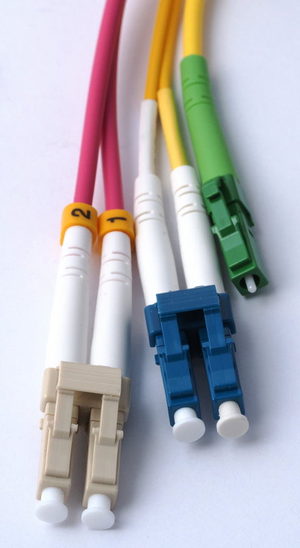
The simplex connector shows the exposed ferrule. As shown in Figure 5, fiberoptic LC cables can be simplex (a single strand) or duplex (two strands). A duplex cable ends in a duplex LC plug that plugs into a duplex transceiver equipped with two receptacles. A simplex cable likewise has a single LC plugs at either end, which plugs into a simplex transceiver with only one LC receptacle. Figure 5 also shows that the external plastic jacket can have considerably different diameters. This is one more reason for not manually mounting connectors onto bulk cable. You would need to source and stock a different connector type for each jacket diameter. In addition, the color of the connector indicates the type of fiber and the geometry of its end (although these standards are not always followed), so for each jacket diameter you would need to stock connectors of two or three different colors. Let the cable factory do these things for you. The outer jacket of LC data fiber can have any color, but frequently:
The OM or OS specification is often printed on the outer jacket. The plug and receptacle may be color-coded:
The strain relief attached to the plug may also be color-coded:
Do not use multimode transceivers that emit different wavelengths at opposite ends of the same multimode duplex link. Just to be safe, use identical transceivers (same brand, same model) at the ends of the same multimode duplex link. Fiber endsThe ends of duplex optical fiber can be polished in different ways:
Simplex singlemode fiber uses APCangled physical contact end polishing. The end surface of the fiber is polished in a plane not perpendicular to the fiber axis, but offset from it by 8°. Light that runs through the fiber and reaches its end is always partly reflected back by the end of the fiber. The 8° offset caused this reflected light not to be reflected along the fiber axis, but at an angle of 16° to it. The reflected light hits the surface between core and cladding at an angle that exceeds the total reflection angle, most of the light passes through this surface, and is absorbed by the cladding and plastic coating. After multiple reflections, virtually nothing of the original light reflected by the fiber end remains. When the ends of two LC/APC fibers are juxtaposed, e.g. by using a coupler, the respective end faces are parallel to each other. This guarantees minimal transmission losses. On the other hand, coupling together an APC and an UPC fiber causes a mismatch and significant losses. A low-loss coupling of APC fiber requires the orientation of the oblique fiber end-faces to be tightly controlled during polishing. There is no such requirement in UPC and PC fiber. An APC fiber should not be plugged into transceivers made for PC or UPC fiber, nor coupled to a PC or UPC fiber. 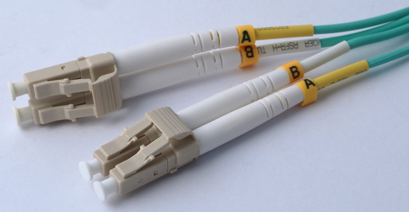
Duplex cables are cross-connected, i.e. the rightmost strand at one duplex LC connector is joined to the leftmost strand at the other connector (Figure 6). The two strands are often, but not always, identified by A and B labels, 1 and 2 labels, and/or one yellow and one white sleeve. Most duplex plugs can be partly disassembled, and reassembled with the cables in reversed positions at one end (yielding a straight-through cable). This is necessary in some cases, but a straight-through cable will not work if used where an ordinary (cross-connected) cable is expected. 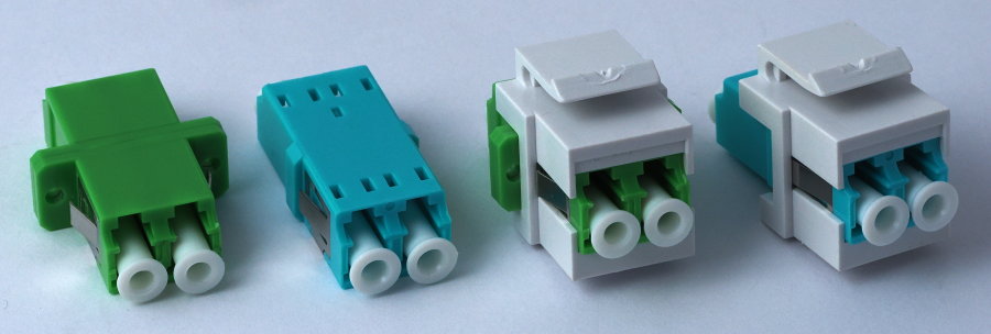
LC couplers are used in the same way as RJ45 couplers on network distribution panels. One side of the coupler is connected with a short patch cord to a network device in the same rack, the other side is typically connected to a long cable that leads to a wall socket in a different room or building. Duplex couplers are available to join together two duplex LC cables (Figure 7). These couplers contain no optics, their only function is to keep the two duplex plugs properly aligned with their ferrules exactly facing each other. Except for the color, which indicates the type of connected fiber, all LC connectors are dimensionally identical because the LC plugs and the ferrules of different fiber types are identically sized. It is therefore physically possible to use a coupler to join two incompatible types of LC cables. Choosing couplers and cables of the correct standard colors may help to avoid this pitfall. Keep in mind that the cable connected at the rear of a coupler is usually invisible from the front of the panel. Therefore, you should always make sure you are not using couplers of the wrong color. The leftmost example of coupler is for mounting on adapter-standard panels commonly used for fiberoptics. Note that this coupler is equipped with side "wings" for attaching to a panel with two screws, as an alternative to the built-in steel spring. The two examples on the right are for mounting into Keystone-standard panels that allow different types of connectors to be mounted into the same standard-sized rectangular holes. Other available connector types for Keystone panels include e.g. RJ45, USB 3.1, BNCbayonet Neill–Concelman, HDMI, RCARadio Corporation of America audio, and 2.5, 3.5 and 6.3 mm audio jacks. Note that one of these couplers (second from the right) is of the same type as the leftmost one in the figure (except for the additionl Keystone adapter), and is also equipped with wings for screw-mounting on an adapter-standard panel. The two side wings prevent two of these couplers from mounting into adjacent holes on Keystone panels, which are spaced only 4 mm from each other. Keep this in mind when ordering couplers to mount into Keystone panels. Several sellers advertise this type of Keystone coupler with wings (e.g. on Amazon) without mentioning its limitations. On the other hand, it is often impossible to find reasonably priced Keystone LC couplers of all necessary colors without wings, so you may need to purchase Keystone couplers with wings, and either cut off the wings with a Dremel tool, or mount alternate winged and wingless couplers along the panel. For 19" rack network distribution, panels with either Keystone and adapter-standard holes are available. Both types of panel allow up to 24 couplers to be mounted on a row spanning the width of the panel. Unlike Keystone panels, adapter-standard panels are typically used only for fiber couplers. Couplers for adapter-standard panels are also available in double and quadruple width (i.e. with front receptacles for four or eight LC simplex plugs). These couplers are used in high-density panels for tens or hundreds of strands, and require a special type of distribution panel or distribution tray. I have been looking for, but failed to source, green simplex couplers for Keystone panels. I make do with a green duplex coupler, leaving one of the two sides unused. Simplex cables and transceiversThe reason for duplex and simplex cables needs an explanation. An optical fiber is intrinsically capable of simultaneously transmitting light in opposite directions, unlike an electrical wire that can transmit an electrical current only in one direction at a time. However, it is technically simpler to transmit light only in a single direction along a fiber, since this requires only a light source at one end and a light detector at the opposite end. Therefore, with this simple (and cheap) technology one needs two parallel fibers for bidirectional communication, i.e., a duplex cable. On the other hand, for long-haul connections, where the cost of fiber is significant, it may be desirable to use only one fiber, i.e., a simplex cable. In this case, both a light source and a light detector are needed at each end of the fiber. The optical paths from the source and to the detector must be joined together at one end of the link, and split apart at the opposite end. The joining and splitting of optical paths is done by a passive (i.e., not electrically powered) optical device called a beamsplitter. In its simplest implementation, used also in simplex transceivers, it is a thin glass plate oriented at 45° to the axis of the fiber. It works by reflecting a portion (often 50%) of the incoming light in a direction at 90° to the incoming, and transmitting the rest along the original direction. If we follow the light path from the source at one end of the fiber to the detector at the opposite end, we see that the first beamsplitter directs some of the light (half, if we simplify) away, in a direction that wastes this part of the light. The rest enters the fiber, exits at the opposite end, and hits the beamsplitter in the other transceiver. Here it is split again into two beams. One beam hits the opposite light source and is wasted. The remaining one-quarter of the original light hits the detector and is converted into an electrical signal. The second transceiver likewise sends light to the first transceiver, completing the return path of the bidirectional connection. The problem with this setup is that some light is also reflected back at either end of the fiber, and ends up hitting the wrong detector. To eliminate this problem, three different technologies are used:
A consequence of the more complex construction of simplex transceivers is that they tend to cost more. Therefore, they tend to be used where their higher cost is offset by the lower cost of a simplex versus duplex fiber, i.e., in long-haul communication. For short-haul communication, duplex transceivers and duplex fiber are usually more convenient. Also, the two simplex transceivers meant to work together differ from each other, and their specifications must complement each other. For this reason, it is safest to buy these transceivers as a matched pair, to avoid potential problems. The two duplex transceivers meant to be used at the ends of the same link, instead, are identical to each other. 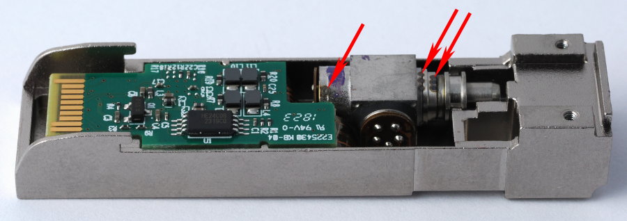
Figure 8 shows the internal parts of a simplex transceiver. The beamsplitter is housed in the small cubic metal box. This box has three optical ports. The laser sits at the leftmost port in the figure (marked with a dab of violet paint). The detector sits at the lowermost port in the middle. The rightmost port is optically coupled to the ferrule of the optical cable. The red arrows point to multiple laser-soldered joints, apparently used to immobilize the various metal parts at the correct reciprocal positions during assembly on the production line. In order to offset the transmission losses of beamsplitter as well as long-haul fiber, the lasers of simplex transceivers tend to be more powerful than the LEDs normally used in short-haul connections. Most laser transceivers can throttle down the power of the light source, and do so during the initial handshake communication with the opposite transceiver when the link comes up. However, there are limits to the range of power a solid-state laser can emit. Simplex transceivers designed, for example, for a maximum fiber length of 20 km often cannot throttle down their emitted power enough to avoid damaging the detector of the opposite transceiver if the fiber length is much shorter than 20 km. The end result is that the detector overheats and burns out. 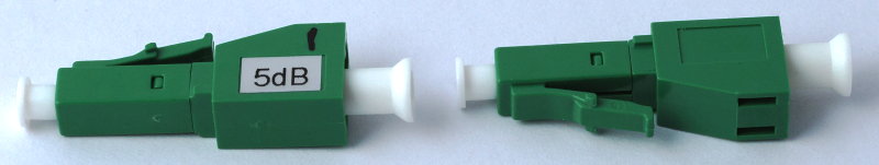
To avoid detector burnout, when using short-haul fiber one should insert one or more attenuators at one or both ends of the fiber. These attenuators (Figure 9) are relatively cheap passive components that contain a short length of optical fiber, made from a special material that acts as a neutral filter and housed in a ceramic ferrule. Typically, attenuators are individually tested and come with a test report. The ones I use have a ±2.5% tolerance on the nominal value. Typical attenuation values are 5, 10 and 15 dB. Variable attenuators are also available, but far too expensive to be interesting to me. I am only aware of simplex singlemode LC attenuators with APC (8° slanted) or UPC ends. These attenuators are color-coded green or dark blue, respectively. As a rule, there is no need for multimode attenuators because multimode transceivers do not transmit amounts of energy sufficient to damage their photo-detectors. A duplex singlemode fiber can be equipped with pairs of simplex attenuators if necessary. With my simplex singlemode transceivers rated for a 20 km maximum length, I can use up to two 5 dB attenuators (in total 10 dB) with a short (20 m) singlemode APC fiber. Three attenuators (in total 15 dB) prevent the link from functioning. Variable optical attenuators are available, but their price is orders of magnitude higher than fixed attenuators. I learned by direct experience that the risk of burning out singlemode transceivers by using too short an optical cable is very real. In my first attempt to use a singlemode simplex link with a 10 m long fiber, I used a pair of 20 km-rated transceivers without attenuators. The link worked perfectly for about one month, until one day one of the receivers started logging more and more errors, until the link was switching off and on every 2-3 seconds. Shortly thereafter, one of the transceivers (the one housed in an SFP+ network card in a PC, not the one in the router) completely died and the link went permanently down. Do not use identical singlemode transceivers (same sending wavelength and same receiving wavelength) at opposite ends of the same singlemode simplex link. Do use identical singlemode transceivers (same sending and receiving wavelength) at opposite ends of the same singlemode duplex link. Before powering on a new singlemode (simplex or duplex) connection, make sure that the fiber connection is not too short for the chosen transceivers. Add in-line attenuators on each fiber if necessary. If uncertain, test with 15 or 20 dB attenuation on each fiber first, then gradually reduce the attenuation until the link starts working. Once the link works reliably, permanently leave any remaining attenuators in place.
SummaryThe hardware used in optical data networks is much more varied than the hardware used in copper-cable Ethernet networks. You need to master the technical basics and terminology of optical network hardware to avoid costly mistakes when selecting optical hardware. Singlemode transceivers are typically made for long-haul connections (several km to hundreds of km between repeaters). If used with short fiber runs, the transmitter laser may burn out the detector in the transceiver at the opposite end of the link. Add in-line attenuators to try and prevent this, or use 10G-LR specified transceivers without attenuators. Better yet, do not use singlemode fiber and transceivers for a short-haul link. Use multimode instead. |