Extending asymmetric VLANs onto a second D-Link DGS-1210 series smart switch
On an earlier page, I discuss how to create a set of asymmetric VLANs on a D-Link DGS-1210 series smart switch. I later decided that I needed to extend these VLANs onto a second physical switch at a separate location in the same LAN. In practice, the two physical switches must behave like a single virtual switch distributed at two distinct locations. My home network is constrained by the distribution of available cable conduits already built into the walls. These include empty conduits originally installed for video surveillance by a previous owner of the building. These conduits are too few, too narrow (only one Cat 6 installation cable fits in each conduit) and not optimally placed for a home data network. It all boils down to the constraint that the second switch must sit in a different physical place than the first, and that connection between the two switches is limited to one, or at most two, 10 m long Cat 6 copper cables. The amount of traffic between the two switches is not expected to be very large. The heaviest traffic is expected to take place among ports of the same physical switch, and a 1 Gbps connection between the switches is estimated to be sufficient. In particular, Internet access runs at much less than 1 Gbps on my mobile network modem (it tops out between 62 and 85 Mbps download in my tests repeated at different dates, and a small fraction of this in the opposite direction), so the link between switches is not the Internet access bottleneck. The main advantage of using a single link between switches is that this configuration only uses one port on each switch and a single Cat 6 cable. A second Cat 6 cable between the locations of the two switches is already installed, and can be used for link aggregation if the planned single link should prove to constitute a bottleneck. This second link could also be used as a redundant connection if the first link should go down for any reason. I decided to test link aggregation to learn how it works in practice, even though it may not be required in my system. The D-Link DGS-1210 series of smart switches supports either static aggregation or LACP (Link Aggregation Control Protocol). This provides two alternative configurations to test. Static aggregation expects the aggregated links to remain unchanged, while LACP can dynamically manage unplanned events like one of the links going down, or a port forcing a speed downgrade to 100 Mbps. LACP is not a substitute for load balancing, but can effectively use aggregated links on a per-flow basis (true load balancing works on a per-frame or per-packet basis). HardwareThe second switch for the configuration discussed on this page is a DGS-1210-10MP. Except for its relatively large PoE budget, it has the same capabilities of the DGS-1210-10 used for the original one-switch VLAN configuration. At present, the DGS-1210-10MP is the largest (in terms of PoE power budget) fanless smart PoE switch available from D-Link. The D-Link DGS-1510 series of smart switches has a few potentially interesting additional capabilities (e.g. faster backplane and 10Gbps SFP ports) over those of the DGS-1210 series, but all DGS-1510 models have cooling fans. Fanless operation is a requirement in my case, because of the planned use of these switches in a residential setting where fans are too noisy. PrerequisitesYou may wish to review the prerequisites discussed on my earlier page. In addition, two, instead of one, DGS-1210 switches are needed. If ports 9 and 10 of each switch are not available, or are not fitted with suitable SFP modules, use other ports and modify the configuration procedure accordingly. The two ports 10 of the switches can be connected together at the start of this exercise, but not the two ports 9 (doing so would create a loop). The two switches used for this exercise are hereby called switch 1 (already configured with VLANs) and switch 2 (not configured except for IP network configuration, password etc.). Intended resultsAs mentioned above, the main purpose of this exercise is to extend three asymmetrical VLANs already configured on switch 1 to switch 2, using a single physical link between the two switches. A secondary purpose is testing how link aggregation works in practice, by aggregating a second link to the first one connecting the switches.
Some thought must also be paid to the choice of which ports to use for interconnecting the two switches.
The DGS-1210-10 has in total 10 ports that are essentially identical to each other, but for the fact that
two of them are equipped with SFP receptacles instead of RJ45 sockets. In this case, the choice of which
ports to use for interconnections has essentially no implications. 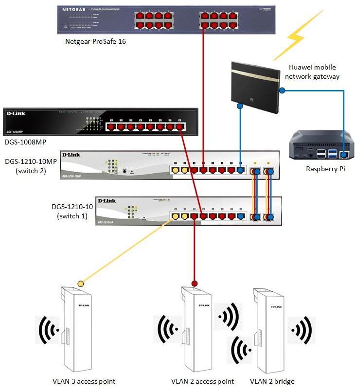
The above figure shows the desired structure of the LAN with the two smart switches discussed on this page and connected equipment. VLAN 1 is indicated in blue, VLAN 2 in red, and VLAN 3 in yellow. For simplicity, firewalls and individual computers (with the exception of a Raspberry Pi used for network surveillance) are not shown. The wireless connection between VLAN 2 access point and VLAN 2 bridge is a necessity dictated by the lack of cable conduits suitable for CAT 6 cable between the ground floor and the higher floors. VLAN configurationOn switch 2, configure three asymmetric VLANs in exactly the same way as already done on switch 1, as described here. Switch configurationPort 10 of both switches is going to be used as the first link connecting the switches. This port is accessible to all VLANs, and therefore can be used to extend all three VLANs from switch 1 to switch 2. 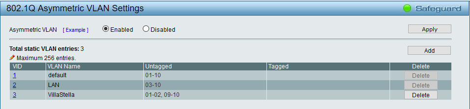
On switch 1, the three VLANs shown in the above figure are already configured. 
The first task is reconfiguring the three VLANs as shown above. Open the 802.1Q Asymmetric VLAN Settings dialog (above figure). In this dialog, click the VID of VLAN 1. This displays the VID Settings dialog. 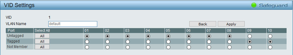
In the VID Settings dialog, tick the Tagged radio button of ports 9 and 10 as shown in the above figure, then click Apply. Repeat the procedure for VIDs 2 and 3. In VID 3, additionally add untagged port 8 to this VLAN. Ports 9-10 will be aggregated to link the two switches, so we need to add a third port where we will connect the mobile network gateway that provides Internet access. Port 8 is already part of VLAN 1 and VLAN 2, so we do not need to add it to these VLANs. Don't forget to click Apply for each VLAN. 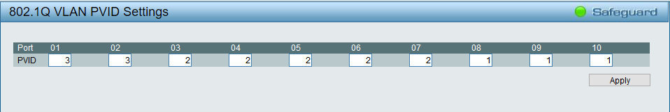
In the 802.1Q VLAN PVID Settings dialog, assign port 8 to VLAN 1. Click Apply. Save the configuration. Duplicate the above configuration on switch 2. If not already done, connect ports 10 of the two switches with a suitable Cat 6 cable or duplex optical fiber. Test VLAN 1 on both switches. In terms of VLAN functionality, it should make no difference whether you are testing VLAN 1 with a computer connected to either switch 1 or switch 2. A computer on VLAN 1 should be able to ping any other computer connected to any VLAN on switches 1 and 2. Repeat the tests on VLANs 2 and 3 to verify that these VLANs can communicate with computers on VLAN 1, but cannot communicate with each other. Link aggregationLink aggregation is called port trunking on D-Link switches. It is just one of several different names for the same thing. 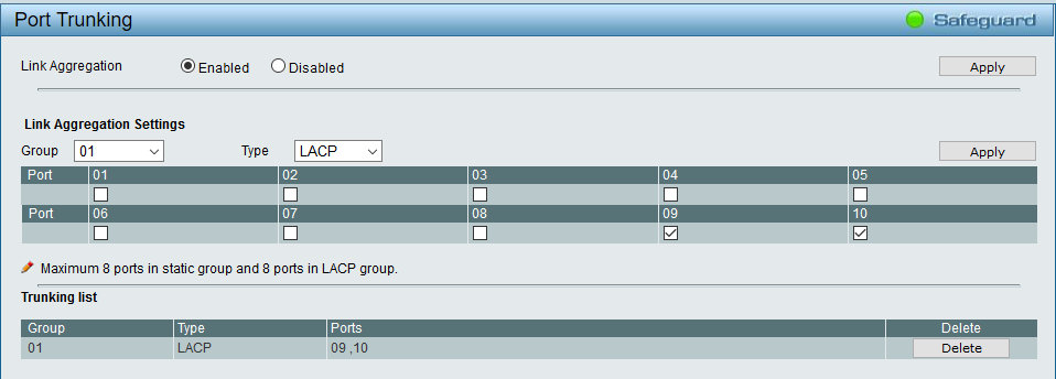
On switch 2, in L2 Functions/Link Aggregation/Port Trunking, tick the Enabled radio button, then click Apply in the same dialog section. Tick the checkboxes of ports 9 and 10 in the Link Aggregation Settings dialog section, then click Apply in the same section of the dialog. This creates a new entry in the Trunking list section of the dialog (above figure). Repeat the above configuration on switch 1. Connect port 9 of both switches with an Ethernet cable. Now it is safe to do so, while before aggregating ports 9 and 10 the spanning tree algorithm would detect ports 9 and 10 forming a closed loop, and disable one of the two ports (or, if spanning tree detection is disabled, ports 9 and 10 would continue to re-send the same frames to each other in an endless loop, and become unresponsive). Testing the aggregated links is not straightforward, short of generating large amounts of traffic between the two switches and measuring the effective speed of the aggregated links, which in this case should be up to roughly 2 Gbps. The easiest way to verify that the two links are aggregated is by observing that the activity LEDs of both port 9 and port 10 are blinking (asynchronously from each other) when data is transmitted between the two switches. LACP allocates ports of an aggregated link on a flow basis, not on a packet basis (at least in these switches), so it is entirely possible for traffic along the aggregated links to use only one of the physical links on a short-term basis. There is a second dialog for configuring LACP, but you do not need to change any of the default settings (and changing anything here may prevent link aggregation from working). In particular, it does not hurt for LACP to be active on all ports, including those not aggregated.
LACP establishes and dynamically maintains the aggregation. This involves some overhead processing and
extra network traffic across the aggregated link, but LACP can manage changes in the availability and
speed of the aggregated ports (e.g. if a port should stop working, or request a drop in link speed from 1G
to 100M). Static link aggregation is simpler, but as far as I understand, it cannot dynamically adapt to
link changes and would just stop working if something happens to the link. The switches at both ends of
the aggregated link must be set to the same type of aggregation (either LACP or static). As a matter of
fact, D-Link recommends that LACP be always used instead of static aggregation. Concluding remarksJoining two smart switches of the DGS-1210 series with a single link and configuring the Ethernet ports using this link as tagged can allow asymmetric VLANs to span across switches and the latter to behave, in essence, like a single distributed switch. Implementing this functionality, however, requires an understanding of the logic involved in the configuration of VLANs, tagged ports and (if used) aggregated links. If multiple connections between the switches are available, link aggregation can be used between the two switches to increase bandwidth and add link redundancy. LACP, recommended by D-Link for this use, appears to be the most reliable alternative for link aggregation. If asymmetric VLANs are not available on your network switches, and your switches do not support static L3 routing, the only alternative to replacing the switches is to use separate IP routers to connect symmetric VLANs implemented on the switches. The two solutions, however, differ in several respects, in particular because asymmetric VLANs are a layer 2 solution (and are port-based in the present implementation), while IP routing is a layer 3 solution and (literally) adds a whole new layer of complexity. |