Polaroid SprintScan 4000The Polaroid SprintScan 4000 scanner for 35 mm film, probably introduced around 2000-2001, has a specified optical resolution (on the film side) of 4,000 dpi, just like the high-end Nikon scanners. It accepts mounted slides or film strips with an image width of 24 mm. Therefore, this model sounds potentially interesting. The plastic case is fiddly to open. The internal design is quite similar to the Nikon scanners (no surprises here), including the light path and focusing mechanisms, but the light source of the SprintScan 4000 is a fluorescent tube and the CCD sensor has four rows of pixels, each with an integral color filter (R, G, B and NIR). The physical size of this unit is closer to the Coolscan 8000/9000 than to the Coolscan models for 35 mm film. The SprintScan 4000 solves the most irritating problem I had with a Nikon 35 mm film scanner, i.e. that after scanning half of a film strip, I had to extract the film holder, rotate it half a turn and reinsert it to scan the other half of the strip. The SprintScan 4000 does away with this limitation by letting the film holder exit through an opening at the rear of the scanner (in addition to the aperture at the front, used to feed the film holder into the scanner). The lens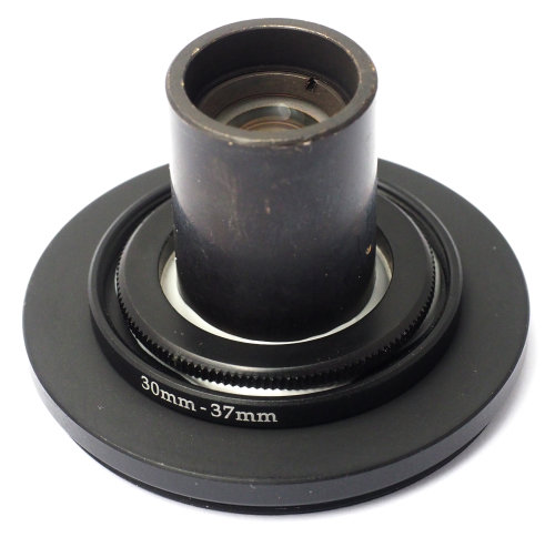
The lens of the SprintScan 4000 is small and housed in a cylindrical, blackened brass barrel without markings, of a diameter just below 21 mm and just over 28 mm long. All optical groups apparently have been inserted into the barrel from the end facing toward the sensor, and fixed in place with a retaining ring sealed with thread sealant. I can see at least nine reflections of lens surfaces by peering into the lens (of different colors, indicating different types of multicoatings). There is also a fixed aperture roughly at the center of the lens. The approximate focal length is 40 mm, the lens speed f/3.6 judging from the size of the film-side front element. The internal aperture seems to prevent off-axis light from passing through the lens, rather than reducing the lens speed. The optical scheme is asymmetric. Theoretical evaluation of the lensExcept for the 0.7 mm of the protecting window on the sensor, there is no glass in the optical path of the scanner. As far as I know, this scanner did not use film carriers with glass. An f/3.6 lens is not so sensitive to glass plates of moderate thickness in the optical path, so I do not expect the optical performance to be substantially lower on digital cameras with filter stacks of ordinary thickness. The sensor chip is large, with a length of the active area of 43 mm. Therefore, this lens magnifies the subject by 1.8 x onto the sensor, unlike the lens of the Coolscan 8000. 43 mm is almost enough to cover the diagonal of a 36 by 24 mm frame, and since full-frame sensors are just a bit shy of this size, the lens should provide a good image on full-frame sensors at this magnification, possibly with the exception of the extreme corners (I don't have a full-frame camera to test this). The 4,000 dpi specification applies to the subject side with the lens in its original orientation, so the lens resolution on the image side should be 4,000 / 2 / 1.8 = 1,100 lppi. This is a respectable resolution, compared to the CoastalOpt 60 mm Apo, and on par with some of the other best macro lenses. Reversed, the lens of the SprintScan 4000 should be optimized at 0.55 x (i.e. 1 / 1.8) and cover a Micro 4/3 sensor (43 mm / 1.8 = 23.9 mm diagonal, which is more than the 21.6 mm diagonal of Micro 4/3). Reversed, it should provide 4,000 dpi (2,000 lppi) on the sensor side. This is enough to match a 2,000 * 2.5 * 17.3 / 25.4 = 3,405 by 2,559 pixels sensor, or 8.5 Mpixel. 16 and 20 Mpixel sensors of Micro 4/3 cameras clearly outresolve this lens, but its image quality is acceptable if not a direct competitor against a good macro lens. 0.55 x on Micro 4/3 gives a field of view of 31.4 by 23.6 mm, i.e. a little less than the field of view at 1x on a full-frame sensor. As a whole, however, the lens appears to be a better match for full-frame sensors than smaller ones. The lens in practiceI chose to mount the lens reversed in an improvised adapter (above picture) that happens to provide a good mechanical fit with minimal risk for misalignment and decentering. The barrel of the reversed lens, as is, provides a nice, shallow lens shade on the subject side that does not significantly reduce the working distance. Reality is somewhat different from theory in this case. The large majority of lenses provide a significantly better resolution in the central portion of their image circle than at the edges. This is so because it is much easier to correct aberrations at the center of the image circle than at its edges. Improving the image quality in peripheral regions of the image circle almost invariably improves also the resolution in the center. The center of the image circle, therefore, may end up performing better than actually needed. A lens designed for use in a scanner (or at least, in a scanner of good quality) requires the specified resolution to be delivered up to the edges of the image circle. In other words, to provide a minimum resolution of 4,000 dpi across the whole image circle, a lens may start with a higher resolution at the center of the image circle (for example 5,000 dpi) and gradually degrade to 4,000 dpi at the edge. With a sensor that captures only detail corresponding to the 4,000 dpi specified resolution of the lens, image quality will be equally good across the frame, and both designers and customers will be happy. Micro 4/3 demands a high lens resolution, but requires a smaller image circle than produced by these scanner lenses. If the image circle of the lens is much larger than the sensor diagonal, it is quite possible for a lens to completely cover a small sensor with the best part of its image circle (for example, an area producing 6,000 dpi or more), and for the lens, on this sensor with smaller pixels than the original target, to perform significantly better than its factory specifications. That is, if we are lucky and everything works as hoped. Lens testsI made the following tests with different amounts of extension between lens and camera, to try and identify which magnification range provides good results. First are reduced frames, and then 1:1 crops of images of a steel ruler. The whole frame (topmost in each set in the illustrations below) allows the image magnification to be computed (rulings in the images are 0.5 mm apart, while the sensor width is 17.3 mm wide). The 1:1 pixel crops allow a visual evaluation of the available image detail. I am showing below crops of the center (rightmost column in the illustration) and edge of the image (leftmost column in the illustration). 
Top: whole frame, reduced. Bottom left: edge. Bottom right: center. 
Top: whole frame, reduced. Bottom left: edge. Bottom right: center. 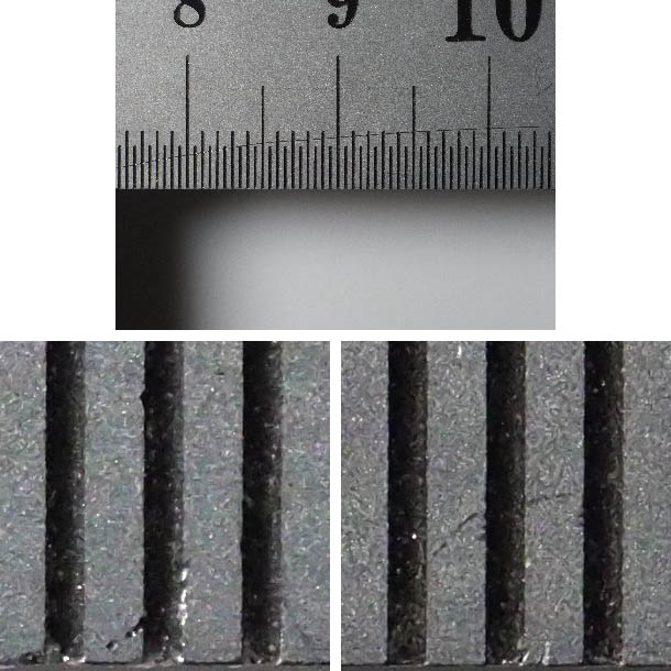
Top: whole frame, reduced. Bottom left: edge. Bottom right: center. 
Top: whole frame, reduced. Bottom left: edge. Bottom right: center. 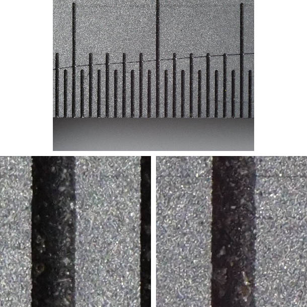
Top: whole frame, reduced. Bottom left: edge. Bottom right: center. 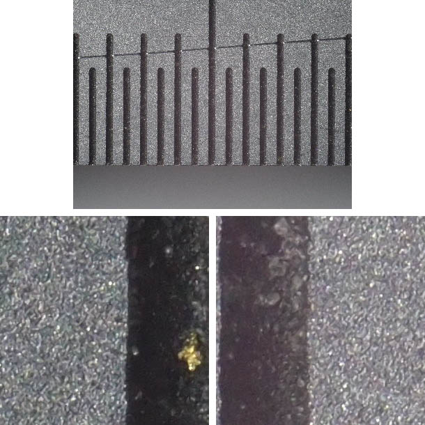
Top: whole frame, reduced. Bottom left: edge. Bottom right: center. The amount of extension (in addition to adapters at the lens and camera ends, which are in total another 13 mm) and magnification on Micro 4/3 are listed in the table below. Degradation of image quality with a 7 mm or 14 mm extension ring is visible in the 1:1 pixel crops, although it might be acceptable if the image is not very large. A very slight degradation is still detectable at the edges with stacked 7 and 14 mm rings. Using one or two stacked 28 mm rings produces the best IQ, with edges essentially identical to the center. Above this range of magnification, image quality declines because of flare, rather than loss of resolution. Preliminary attempts indicate that this flare can at least be lowered, and perhaps eliminated, with internal baffling and/or flocking. Flocking the internal surface of the lens shade may also help. It may be possible to push magnification a little higher once flare is no longer a problem, but I have some doubt about expecting excellent results at 3x or higher. Working distance is roughly 90 mm at 0.77x, 60 mm at 1.4x, and 53 mm at 2.1x.
Chromatic aberrationsThe following figure shows a ruler on a microscope slide, slightly inclined sideways with respect to the normal to the optical axis. The out-of-focus extremities are a way to detect whether any axial chromatic aberration is present. Axial chromatic aberration manifests as different colors on different sides of the focus plane (often cyan on one side and magenta on the other). Transversal chromatic aberration would show as a double fringing near the edges of the frame, with the same color of each fringe facing toward the same direction (e.g. cyan toward the center and magenta toward the sides of the frame). Strictly speaking, transversal color aberration is better detected with a ruler entirely in focus, but I think you can trust me on the fact that it would make no difference in this case. 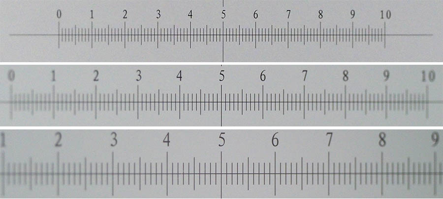
Top: imaged at 0.77x. Middle: 1.4x. Bottom: 2.1x. Not to scale. The above images show that there is no detectable axial chromatic aberration. There is no hint of color fringing of any type. There is therefore also no detectable transversal chromatic aberration, although a different test would be better for this. There is a hint of what the Japanese call nisen boke (two-strokes bokeh) at the right end of the ruler, especially at the higher magnifications. This side corresponds to the ruler being placed farther from the lens than the focus plane. The defocus is creamier in the opposite direction. Since most of the time the unfocused parts of a macro image are farther than the focus plane, it would have been better to have the creamier defocus on the farther side. However, considering that the lens was not designed for this use, and that the lens performance is otherwise excellent, this is a minor quibble. Most modern lenses with significantly asymmetrical optical schemes have an asymmetric defocus about the focus plane, as a consequence of overcorrection of spherical aberration. The optimal 0.55x magnification derived from the construction of the scanner is close to the 0.60x that in practical use gives very slightly worse edges than center (on Micro 4/3). Edges are, most likely, further degraded on a full-frame sensor. The thickness of the built-in filter stack of the camera may play a role in this degradation, and the lower filter stack thickness of DSLRs, compared to Micro 4/3 cameras, may alleviate this effect and not make it twice as bad as in the present test. 0.77x is the best tested magnification on Micro 4/3 in practice, still quite close to the nominal magnification of the lens as used in the scanner. As a whole, I would recommend this lens as optimal for work from approximately 0.75x to 1.5x, reversed on Micro 4/3. ConclusionsThe lens of the Polaroid Coolscan 4000 film scanner is excellent for applications that include stacking, at magnifications between 0.75x and 1.5x. Image quality is excellent and working distance relatively high. This lens shows no chromatic aberration, either axial or transversal. |