Variable NIR-pass filter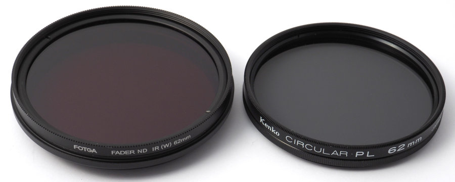
Variable NIR filters made in China (Figure 1, left) are nowadays routinely advertised in online shops like eBay and Amazon. They are based on a stack of two polarizers with an added deep-red filter. By rotating the front polarizer relative to the rear one, the nominal bandpass wavelength can be changed, according to a scale on the filter ring, between 530 nm and 750 nm. The front part of the filter actually rotates freely 360°, just like in a normal polarizer, but the scale covers only an angle of about 80°. These filters are not cheap, but I had a chance to buy one at a reasonable price, quite possibly from an original disappointed owner who wanted to get rid of it. This gave me a chance to examine and test this type of filter. Makeup of a variable NIR filterOptics
It is well known that a stack of two linear polarizers acts more or less like a variable ND filter, when
the two polarizers are rotated with respect to each other. With the polarization axes crossed
perpendicularly to each other, extinction (i.e. the absorption of light) is highest. Almost two decades
ago, in my first experiments in NIR photography, I observed that crossed polarizers designed for camera
use typically achieve an almost complete extinction in VIS, except for a slight purple
transmission, but remain significantly transparent in NIR even when rotated to full extinction. Filter mountMechanically, the metal filter mount of this filter seems well built, but is larger and thicker than the typical mount of polarizers of the same diameter. The fact that it contains both a rotating and a fixed filter disk only partly accounts for this. A surprise with this filter is that, although it is specified as a 62 mm filter and screws into lenses with 62 mm filter mounts, its front thread is 67 mm, so the lens cap no longer fits on the filter and you need a 67 mm lens cap. No doubt this construction is meant to prevent vignetting when using the filter on a wideangle lens (and this may explain the "W" on the filter ring). However, it also has drawbacks, discussed below. Once the filter is mounted on the lens, the large diameter of the filter ring prevents a lens shade from being mounted or dismounted. This is true even of the larger lens shades that mount on a proprietary bayonet at the front of the lens barrel. With some effort, it is possible to screw the variable NIR filter onto the Olympus 12-40 mm f/2.8 with its scalloped lens shade already mounted. However, the filter protrudes so much at the front of the lens, that the lens shade becomes essentially useless. There is no way to mount this filter on the OM System 40-150 mm f/4 with its deeper lens shade. Thus, unless you already have, or purchase, suitable 67 mm lens shades, with this filter you are forced to shoot without a lens shade. 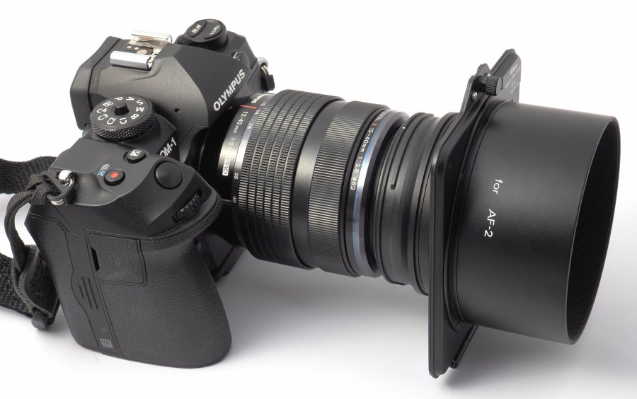
The only lens shade suitable for this filter that I could find in my boxes is a legacy Nikon AF-2 gelatin filter holder (Figure 2). Unfortunately, with its dedicated 82 mm lens shade it vignettes on Micro 4/3 at focal lengths shorter than 25 mm. A rubber lens shade that can be folded back in two or three stages is probably the most useful type for this filter, especially if used on zoom lenses. A scalloped lens shade screwed into the front filter thread would not work, because this part of the filter mount rotates to adjust the filter effect. Image qualityIt is becoming increasingly well documented that images recorded with these variable NIR filters often display large alternating black and red stripes, patches or crosses, especially in the sky portion of a picture and with wideangle lenses. Reviewers often call this problem "banding", and for the sake of simplicity I will follow this terminology. Banding is most often reported by disappointed and baffled buyers, but also by some of the companies most experienced in the conversion of digital cameras to full-spectrum, NIR and NUV imaging. As far as I am aware, no solutions to this problem have been proposed. 
Full images, reduced in size. Some JPG compression artifacts were introduced while scaling down these pictures. A simple way to see a high-contrast version of these red-and-black bands is to look through the filter (adjusted to its maximum transparency), held obliquely in one's hands, at an LCD computer monitor displaying a uniform white background. The number of simultaneously visible artifacts increases as the filter is increasingly tilted. Rotating the filter changes the geometry of the bands. Banding appears in images when the filter is mounted on a wideangle lens. Figure 3 shows two examples, obtained by twisting the camera at different angles about the lens optical axis. These images were recorded on an ordinary camera and are VIS-only images. The artifacts are caused, at least in part, by multiple polarizing layers in the filter and in the computer screen, and are only partly similar to the banding observed with this filter in landscape photography. As a comparison, photographing the same computer screen with an ordinary circular polarizer produces no banding, only near-total extinctions every half-turn of filter rotation. Measuring filter transmissionAdequately measuring filter transmission in the NIR is much easier than in the NUV, principally because it is easy to provide a continuous source of illumination that provides a gap-free emission across the NIR. An incandescent filament lamp (while they are still available) is in fact an almost ideal source of VIS and NIR in this respect. A halogen bulb is somewhat less ideal, in part because it emits proportionally less NIR, and in part because the halogen glow can make the emission spectrum less uniform. Note that, with an incandescent filament lamp, we are not talking about a flat emission spectrum, only a gapless one. If we record a spectrum of the illumination source without a filter in the optical path of a transmission spectroscope (S) and then a spectrum with the filter in the optical path (Sf ), we can normalize Sf as Sl = Sf / S where Sl is the normalized spectrum of the filter, i.e., the spectrum that would be recorded if the illumination source had a flat emission spectrum. This works well if the spectrum is continuous and does not vary across the region of interest by more than approximately one order of magnitude, but the effect of noise becomes important if the spectrum has low-level regions. An incandescent filament lamp has such a low-level region at wavelengths higher than approximately 800-900 nm. Since the transmission spectrum of NIR-pass filters rarely displays sharp peaks and valleys, it is possible to reduce the noise in the spectrometer, mainly by time-averaging a number of successively measured spectra, and even more by programming the spectrometer to reduce its output spectral resolution, usually by performing a moving-window average of the spectrum data. For example, the spectrometer used for my observations has a native resolution of 0.3 nm, but can be set to save spectral data with a resolution of 1 nm instead. Aggregation of data into 1 nm classes partly smoothens out any random noise. Further noise reduction can be carried out in post-processing, at the cost of sacrificing some small-scale details, e.g. by applying a weighted moving-windows averaging to the spectral data. This is easily done with software like Microsoft Excel, or as part of more sophisticated processing with Matlab/Octave. The following graphs were generated with Excel. I used a simple physical setup based on my Lasertack LR-2 solid-state spectroscope and a 40 W incandescent lamp with built-in reflector and frosted bulb. I used an opaque baffle around the light source to shape the light beam, and adjusted the beam intensity by changing the distance between lamp and input fiber of the spectroscope, in order to use as much as practical of the native dynamic range of the spectroscope (the ADC generates 16-bit integers, but the actual dynamic range is lower) without saturating its sensor. I inserted the filter being tested into the optical path immediately in front of the fiber entrance collecting the light to the spectroscope. I also mounted a cosine corrector at the entrance of this optical fiber, to further homogenize the incoming light. I initially inserted a spectralon integrating sphere with input and output windows at 90° to each other between light source and filter, but found that it did not affect the results, other than by requiring a higher light intensity. Transmission spectra
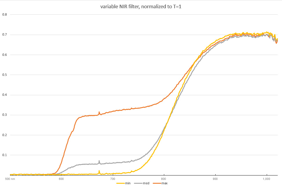
Figures 4-5 show the recorded spectra of an incandescent lamp through the filter set approximately at nominal 530 ("min"), 640 ("med") and 750 ("max") nm values. Figure 4 shows the spectra before normalization against the spectrum of the unfiltered light source. Figure 5 shows the same data after normalization, but in this figure I changed the displayed interval of wavelengths to include more of the cutoff region and to remove the 1,020-1,100 nm region, which was excessively noisy once normalized. Figure 5 is especially illuminating. The filter does not behave as I would expect a true variable NIR-pass filter to operate, which is by presenting a cutoff wavelength that moves along the x axis of the spectrum as the filter control is adjusted. Instead, the filter displays an adjustable transmission band at 600-800 nm, and a non-adjustable transmission band above 800 nm. In a way, this makes the filter potentially more useful than expected, because it is not a replacement for a set of conventional, fixed NIR-transmission filters with different cutoff wavelengths, but something different. The problem of large black artefacts, however, needs to be better understood and corrected before this type of variable filter becomes truly useful. Examining the variable NIR filterBy looking at light reflected by an inclined non-metal reflecting surface (which polarizes light), while looking through a filter and rotating it, it is possible to detect whether the latter polarizes light. If it does, the scene through the filter displays two extinctions per turn of the filter. In my case, I used a polished stone shelf under a window as a reflecting surface. With the variable NIR filter set at maximum VIS transmission, I was able to see that it behaves identically when looked from either direction, and displays two extinctions per turn. This is the behavior expected from a linear polarizer or a stack of parallel linear polarizers. On the other hand, looking through a circular polarizer while rotating it, one sees two extinctions per turn when looking through its rear side, but no extinction from its front side (albeit often I see a slight shift in color instead, an indication that the retardation plate is not perfect). Deconstructing the variable NIR filterFurther investigation requires disassembly of the variable NIR filter. The easiest way is by unscrewing the front retaining ring with an appropriate tool, and removing the outermost optical element. As expected, this variable NIR filter turns out to contain a stack of two polarizers, of which the outermost can rotate freely. A surprise is that each polarizer is cemented to a thin red filter. The two red filters face toward each other. I expected only one red filter to be present, and there is no optical reason for using two identical color filters, instead of just one of double the optical density. Perhaps mass-manufacturing just one type of filter sandwich and using it for both front and rear elements of the stack makes economic sense. However, using two color filters where one would suffice is not a sound design, because it adds two unnecessary optical surfaces that may increase the risk of internal reflections and flare. By the look of these red filters, and the ease with which they wear out against the filter mount, I think they are a gelatin or plastic film. Facing each other, the filters are least likely to suffer mechanical damage, but rain or humidity can make its way through the filter mount and damage or soil the filter surfaces. These red filters do not behave like retardation plates but only like color filters, and each polarizer + red filter sandwich displays two extinctions per turn when looking through either side. Each sandwich acts therefore like, and almost certainly contains, a linear polarizer, which may explain the artifacts experienced by many users of these filters. A better variable NIR-pass filter
Is it possible to correct the banding problem of these filters? My best guess is that the problem
originates from the front element being a linear polarizer. This makes it sensitive to polarized light
from the subject. Instead of a linear polarizer, a reversed circular polarizer could be
used. In this way, the quarter-wave plate receives light first, removes its polarization, and the front
polarizer receives only non-polarized light. Alternatively, the same result can be achieved by adding a
quarter-wave plate at the front of the existing filter. I am unable to say whether any commercial variable NIR-pass filters are made with two properly oriented (as discussed above) circular polarizers. The pictures of all such filters I have seen appear to be identical, although sold by dozens of resellers, so there may be just one model of these filters, produced by a single factory. The filter mount of my specimen carries a "Fotga" brand, but I guess every wholesale buyer can have their order branded any way they wish by the factory producing these filters. I replaced the front optical element of the variable NIR-pass filter with a reversed Kenko 67 mm linear polarizer, the only circular polarizer of this size I found in my box of assorted filters. This is a relatively old filter not designed for wideangle lenses, and its substrate is quite thick. In addition, the optics of this polarizer have a wider diameter than the 62.5 mm of the polarizer + red filter optical sandwich it replaced, so it did not actually fit in the machined groove of the filter mount. The front female thread of the variable NIR-pass filter is deep enough to allow the retaining ring to screw back in, but not enough of the female thread is left exposed to allow a lens shade to be screwed in at the front of the filter. This problem could be solved by forgoing the retaining ring and using the rear mount of a lens shade for this purpose, leaving the lens shade semi-permanently attached to the variable filter with a small drop of thread sealant. A simple visual test of the modified filter with the computer screen was encouraging, with no banding visible at all when looking through the rear of the filter. Photographing the computer screen with the filter on a lens likewise shows no banding. The single remaining red filter is visually slightly brighter than the original with two such filters. Turning the adjustment ring of the modified filter, as expected, generates two extinctions per turn. As a whole, the modified filter performs essentially like the original one, less the artifacts. Looking at the computer screen through the front of the modified filter, instead, still produces the same banding as the original filter. This is also expected, since in this orientation the original linear polarizer is the first optical element that receives light. I don't have a second circular polarizer available to replace the original innermost polarizer of the variable filter, but I have no doubt that doing so will prevent banding also in this orientation. Doing so would remove both original red filters, so a new deep-red filter, e.g. a Hoya 25A or possibly R62 (but Hoya R72 is too dark), would have to be added somewhere (anywhere) in the stack. It can, but does not need to, be placed between the polarizers. Make your own variable NIR-pass filterCompletely building a variable NIR-pass filter from scratch is easier than the above shenanigans I used for testing, and is cheaper than modifying a commercial variable NIR-pass filter. To do this, you need two circular polarizers and a deep-red filter. Additionally, you need to open the retaining ring on one of the polarizers and reverse its optics in their mount, then place this reversed polarizer outermost on the stack.
Just as a reminder, you do have the right to build your own
variable NIR-pass filter and use it for your own non-commercial photography (commercial and for-profit
uses are a different thing), even if the Fotga filter should prove to be protected by all the patents,
trademarks and copyrights of the world. You also have the right to disassemble, study and reverse-engineer
it, and to publicly discuss its design and inner workings. ConclusionsThe Fotga variable NIR-pass filter displays a variable transmission in the 600-800 nm band, and a fixed, higher NIR transmission above 800 nm. This makes it potentially useful in NIR imaging, but its practical usability is limited by heavy artifacts displayed with subjects that emit polarized light. An alternative design that avoids artifacts by using a reversed outermost circular polarizer, together with a red filter and an innermost linear or circular polarizer, is discussed and placed in the public domain. |