Cisco C3560CX-8PC-S switch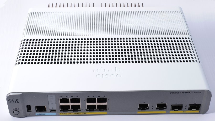
The Cisco C3560CX-8PC-S switch is a rack-mountable Gigabit Ethernet switch designed for "campus LANs" as Cisco calls them, as well as small businesses and small branches. It is somewhat overkill for a typical home network, but with some imagination one may find uses for some of its capabilities even in an advanced home network. In general, a campus network is defined as a group of one or more LANs in a limited geographic area. The term is generally used for networks spanning multiple physical buildings in a restricted geographical area. This switch is part of the Catalyst family of switches and, aside for the limited number of ports, comparable in architecture with the Catalyst 3560 series. However, the C3560CX series cannot use the same firmware designed for the Catalyst 3560 series, and requires CX-specific IOS images. The C3560CX series contains models with 8 or 12 downlink RJ45 Ethernet ports, plus two uplink RJ45 Ethernet ports and two SFP or SFP+ ports. Some models have a few multi-Gb ports, albeit not the C3560CX-8PC-S. The C3560CX series is equipped by default with IP base license, but can be upgraded with the purchase of an IP services license. The hardware and IOS firmware image are the same, but extra functions (mostly related to routing functionality and additional routing protocols) are activated by the IP services license. Most, but not all, C3560CX on the second-hand market are equipped with the IP base license. There is an externally identical C2960CX series of switches equipped only with a LAN base license and, probably, a less powerful CPU. As far as I know, this series cannot be upgraded to IP base or IP services license. There is also an older C2960-C series of externally similar (albeit more plasticky) switches of lesser capabilities, discontinued and typically available at a really low price on the second-hand market.
When choosing a switch in the C3560CX series, I had to decide whether to get one of the models with
multi-Gb ports. There are multiple potential uses for such ports, even in a LAN where all devices are
equipped with 1 Gb NICs. For example, by trunking it is possible to carry multi-VLAN traffic on a single
physical Ethernet cable. This may avoid the need to re-wire a LAN to provide multiple physical Ethernet
cables between network devices at different locations. However, in this case a 1-Gb link speed can quickly
become a bottleneck. On the other hand, on moderate cable lengths, a multi-Gb link may work well at 2.5 or
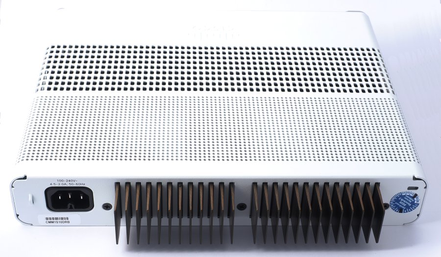
5 Gb even if the cable is not specified to carry such a traffic. In the C3560CX-8PC-S, (albeit not in all models of physically similar switches) all four uplink ports of the switch can be used simultaneously, i.e. they are not "combo" ports where one is forced to use either the RJ45 connector or the SFP receptacle. If desired, one or more of the uplink ports can be used as downlinks (in this switch, there is no hardware or software difference between Ethernet interfaces). An RJ45 serial console port and a mini USB console port are also available, as well as a USB-A port for adding external storage. Using the mini USB console port requires the installation on the computer of a proprietary Cisco USB driver. I prefer using the old-style RJ45 serial console, and installed a cheap expansion card with two serial ports on the PC I use for network administration (modern PC motherboards no longer have built-in serial ports). A normal straight-through Ethernet cable can be used to extend a serial cable by several meters. Administration through the network is of course possible, preferably via SSH. The SSH connection to the switch, however, may be severed by many of the common changes of configuration, or by errors of the administrator. A Mode switch on the front panel, in combination with the LEDs on the panel, can be used to show the system status, PoE status and port speed of the switch. The system status is displayed by default, with port LEDs lighted steady when connected and blinking when traffic is present. After a few seconds in other modes, the mode automatically reverts to system status. The System LED lights up blue during the initial booting phase, then flashes green while booting, and finally turns solid green when the switch is functioning normally. Depending on the installed license type, the switch has IP base functionality or, additionally, IP services functionality (including multiple routing protocols). Mine has the former license type. I prefer to use physically separate routers and switches, since a reasonably priced device generally cannot be expected to excel at both functions. For example, the C3560CX-8PC-S, even with the IP services license, does not seem to offer VPNs. The C3560CX-8PC-S is internally equipped with 512 MB RAM and 128 MB flash memory. The models with "PC" in the model name are equipped with a hefty internal power supply and large external cooling fins protruding from the rear of the case, capable of delivering up to 240 W of PoE+ power in total. This may be enough to power a couple of large switches equipped with PoE+ uplinks, or up to eight WAPs. Up to 1,023 VLANs are possible, but Cisco recommends having no more than 256 to avoid an excessive CPU load. The total switching throughput among downlinks reaches (in theory) 32 Gbps. Cisco's terminology describing which is the front panel, and which the rear, is inconsistent across their product range. In these switches, the panel with network connectors is defined as the front panel. This is just the opposite as, for example, the C900 routers. End of lifeThe C3560CX series, or at least most of its models, will stop selling on April 30, 2024, and will be supported by Cisco until April 30, 2029. This series is meant to be replaced by the C9200CX series. Second-hand valueA used unit should sell for between one-quarter and one-third of the new price. In practice, a second-hand, reconditioned C3560CX clean and in good shape should sell at roughly 380-500 €. Rack ears may add up to 30-50 € to the total. If rack ears must be purchased separately, Amazon (especially in the US) offers third-party replacement ears as good as the original ones at a small fraction of the ludicrously high second-hand prices for genuine Cisco ears on eBay. MountingThe switch is fanless in spite of the PoE power supply, and Cisco recommends leaving at least 76 mm of empty space around the top, sides and rear of the case in order to allow convection cooling. In my experience, leaving an empty space also below the bottom of the case helps to lower the case temperature. Clearly, these switches are not designed for tightly packed rack cabinets. Two screws slots at the bottom of the case can be used to attach the case to a table-top or shelf, a wall, or (upside down) under a shelf or table-top. The cooling fins at the rear of the case work best with the switch in a horizontal orientation, or with the fins pointing upward. An orientation with the fins pointing sideways is the least efficient orientation. However, this is likely to be important only when the PoE load approaches its maximum. Two threaded screw holes are also available, one on each side, for rack ears. The rack ears are equipped with anti-twist tabs that prevent the switch case from sagging. The rack ears do not allow the switch front panel to mount flush with the front of the rack cabinet. Instead, the front panel of the switch projects outward by 25 mm. You cannot mount the rack ears at the rear of the switch, only at the front. You also cannot mount the rack ears in reversed orientation (it is possible in many other Cisco devices). The same threaded holes can alternatively be used to attach the switch case to brackets of a tray (sold separately), which in turn is attached to a flat surface (e.g. above or below a table-top or shelf) with screws. The vented upper surface and sides of the switch case must not be blocked, but it is apparently possible to attach the switch upside-down under a horizontal surface. The total size of the case is 4.44 x 26.9 x 23.8 cm. At 2.27 Kg, this is a relatively small but heavy "brick", mainly because of the large PoE power supply. If you are sure you do not need PoE, you are better off purchasing a different model without PoE support for a lower price, which should also run cooler. If you know you need large amounts of PoE+ on a small number of ports, this switch may be one af the best choices available. This switch does not seem to run any cooler if you switch off PoE in the IOS configuration. Internals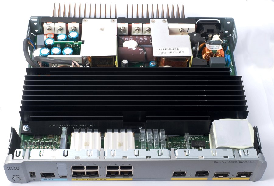
To open the case, disconnect all cables, remove the six screws at the bottom and the three screws on the back panel, then insert a flat-blade screwdriver in the two rectangular holes at the bottom and leverage the case open by sliding the cover backwards. Figure 3 shows the internals. The power supply takes the rear 1/3 of the volume. Keep your fingers away from the power supply even when power is disconnected, because the electrolytic capacitors may still store a potentially deadly charge. A large black heatsink covers most of the mainboard. The casing of the two SFP sockets is covered with a thermal conductive pad that touches the outer case. The front panel is mostly made of plastic, while the rest of the case is metal sheet. Several light guides optically couple LEDs on the mainboard to the front panel, including four unused light guides, placed where the RJ45 connectors for downlinks 9-12 are located in models equipped with 12 such sockets. The mainboard has empty soldering pads for components of these interfaces, and appears to be designed for use in multiple switch models. 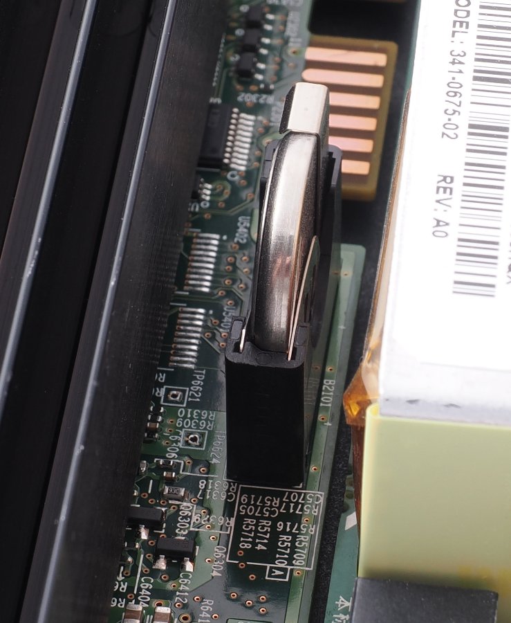
Between the power supply and the mainboard there is a flat battery in a holder, which may need to be replaced every few years. This may be the only (good) reason for a user to open the case. At least, Cisco used their good judgement and did not solder the battery directly to the mainboard just to save 50 ¢, as routinely done by e.g. Chinese manufacturers. I found a single reference to the battery in the 2,162-page Consolidated Platform Configuration Guide, Cisco IOS Release 15.2(7)Ex (Catalyst 3560-CX and 2960-CX Switches) user guide, which says "RTC is battery-powered." I expected the Catalyst 3560-CX and 2960-CX Switch Hardware Installation Guide to say more about the battery, but it never mentions it. If you have read this paragraph, now you know what to do if the RTC clock stops keeping the time when the switch is disconnected from mains. 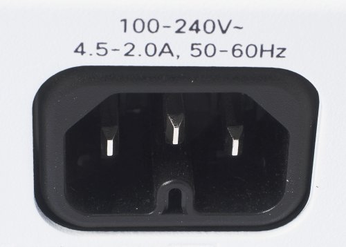
I purchased this second-hand switch from a large German second-hand dealer on eBay. It came with a new power cord, except of the wrong type. As Figure 5 shows, the power cable connector on the switch side must have a deep groove below the ground contact. It is neither the IEC320C13 almost always used in the EU (which was supplied by mistake with the switch), nor the less common IEC320C5 "cloverblade", but the rarely seen (in the EU) IEC320C15. This connector is mostly used in N America, and aside for the deep groove and matching ridge has the same specifications as the IEC320C13. I have a large collection of power cables, but none of the right type. In order to test the switch, I judiciously modified an ordinary molded EU power cable with a Dremel, and got the job done in a minute. I do not recommend you do the same, because accidentally exposing one of the copper conductors by grinding too deep is very easy, and handling a damaged mains connector can kill you. I did it only as a stop-gap measure, while waiting for a proper cable to arrive. The hollow ridge within the mains socket in the above figure suggests that this part may be designed to be cut off with wire cutters, yielding as a result an IEC320C13-compatible socket. However, I decided against attempting to modify this part. The label at the bottom of the router case is not a Cisco label, it is branded Anatel. This is the Brazilian state telecom company, which may originally have purchased a batch of these switches from Cisco and probably had them delivered directly from Cisco with the customized Anatel label. This label suggests that these switches were meant for lease or sale to Anatel customers. Everywhere else on the case, including on the same labels, on the top of the case, and on the front panel, the Cisco branding is well visible. My specimen of the switch arrived exceptionally clean inside and outside, to the point that it got visibly dustier after just unpacking and taking the pictures for this web page. Neither its rubber feet nor rack ears seem to have been ever mounted. Except for slight markings on the plastic of the front panel and some fine external dust, both possibly caused by stacking unpackaged equipment on a shelf, it seems to have never been used in a live installation. There is no command to show the total uptime of a Cisco device, only the uptime since the last reload, so there is no way to be sure. Since its arrival, this switch has been running 24/7 in my home network. ExpandabilityThis switch cannot be equipped with modules, and its internal hardware cannot be upgraded. Cisco support and firmwareProblems in obtaining firmware upgrades for the C3560CX series are the same as dicussed for the C900 routers. SpecificationsThe specifications and capabilities of the C3560CX series are listed here. ConfigurationThe C3560CX series is configured via the Cisco IOS CLI. One version of the firmware, apparently no longer supported, allows for a limited GUI configuration. The GUI software is no longer available from Cisco. Do not purchase one these switches unless you are prepared to configure it via the Cisco IOS CLI. The IOS installed on Cisco switches differs in some respects from the IOS used on routers. For example, port ranges are typically available on switches (to make it faster to configure multiple ports), but not on routers. The L3 functionality of switches is typically more restricted than on routers or combined router-switches. Some Cisco switches entirely lack L3 functionality. Other than these differences, configuring this switch is quite similar to configuring a router. On two earlier pages, I discussed how to create on D-Link switches asymmetric port-based VLANs that do not use Layer 3 functionality (here and here). The Cisco way of working with VLANs is different, and there is no direct counterpart to achieve the same results. On a Cisco switch, you can either manually set a port to access mode and assign it to a single VLAN, or set a port to work as a trunk, which will make it carry all VLANs present on the switch (by inserting the IEEE 802.1Q header, which only switches and routers normally can handle). If necessary, individual VLANs can be manually excluded from a trunk. That's the whole story for data traffic. Additional modes require VTP (see below) or voice VLANs. If the above makes you think that individual Cisco VLANs cannot communicate with each other, you are correct. To make VLANs communicate with each other, in Cisco networks you need layer 3 functionality (in practice, inter-VLAN routing). This is one of the reasons why it is so useful to have some layer 3 functionality in a Cisco switch. If they don't (like e.g. in the C2960-C series, which explains why they are so cheap), you will need a router to make VLANs talk to each other. On Cisco switches, you can use VTP to propagate the VLAN structure across switches, which is a great help if you have multiple switches in the same LAN. Just add a new switch, configure it to join the existing VTP domain, and automagically it will copy the VLAN structure from the existing switches (if it is your lucky day - if not, the new switch may delete all VLANs from the whole LAN, so you better read the VTP documentation carefully and have a plan).
I purchased this switch to expand the number of Ethernet ports available on a Cisco C931-4P router. I am
under the impression that the general advice, when combining a router and a switch in order to implement
VLANs, is to create the VLANs and DHCP server on the router, not on the switch. However,
this post
on Cisco support states that the C921 router (and, I assume by extension, the similar C931) do not support
VLANs. I know for a fact that the C931 accepts most IOS commands necessary to create VLANs and
VLAN-specific DHCP pools, but all my attempts to extend DHCP to attached switches by configuring
helper-addresses on these switches failed. InitializationThe initial part of the configuration is essentially identical to the one I discussed for the C931 router. For explanations, see the discussion of this router here. enable ! set up the terminal emulator window terminal width 160 terminal length 0 ! eliminate the **more** prompt no logging console ! prevent log messages from interrupting your workflow conf t ! assign router and domain name hostname C3560CX ip domain-name <your-domain>.local ! configure SSH crypto key generate rsa 2048 ip ssh version 2 line vty 0 4 ! require a password session-timeout 300 exec-timeout 300 transport input ssh ! require SSH login local ! require username + password exit no ip domain-lookup ! prevent DNS from looking up mis-spelled commands ! create user account username <your-username> password <your-password> ! create non-recoverable password enable secret <your-password> InterfacesThe pre-defined interfaces are vlan 1 and GigabitEthernet0/1 through GigabitEthernet0/12 (abbreviated g0/1 through g0/12). Although this notation usually indicates module/port numbers, this is a fixed configuration switch that can take no modules. Perhaps this notation was used on the C3560CX series to comply with the notation typical of Catalyst switches. However, modern fixed-configuration routers and router-switches like the C900 series do away completely with this notation and only use the port number. Only interfaces g0/1 to g0/8 provide PoE. PoE is activated by default. None of the switch interfaces, not even the ones grouped on the right side of the panel and presumably expected to be used as uplinks, can directly accept an IP address (keep in mind that this is an L2 switch with some L3 capabilities, but not a proper router-switch). An IP address must be assigned to a VLAN, and one or more interfaces assigned to the VLAN. vlan 1, as usual, is the default VLAN and cannot be removed. After assigning an IP address to vlan 1, you can use this address e.g. to configure the switch with SSH. interface vlan 1 ip address 192.168.1.4 255.255.255.0 no shutdown If we do not explicitly declare additional VLANs before using them, they will be created anyway when first used in the configuration. In this case, the switch displays an information message when creating a VLAN. It is not an error message, so you can ignore these messages because they are expected. If you prefer not to see these messages, declare these VLANS first, like in the following example. Note also that the IP address ranges of the VLAN networks cannot overlap. vlan 2 The desired end result in the following configuration example is to assign interfaces:
We further decide to use g0/9 as uplink of vlan 1 to the router. The reason will be explained in the context of DHCP snooping. We begin by creating two interface ranges, one for each of the VLAN we will use. This is not indispensable, but named interface ranges make the configuration easier to decipher. In the interface range macro definitions, note that the space before and after each dash and before and after each comma is required. We then use these ranges to define the interface properties within each of these groups. define interface-range VLAN1PORTS g0/1 - 4 , g0/9 , g0/10 define interface-range VLAN2PORTS g0/5 - 8 , g0/10 , g0/12 interface range macro VLAN1PORTS storm-control multicast level 70.0 30.0 switchport mode access switchport access vlan 1 no shutdown interface range macro VLAN2PORTS storm-control multicast level 70.0 30.0 switchport mode access switchport access vlan 2 no shutdown interface g0/9 exit The stormcontrol commands provide a measure of protection against runaway multicast DoS attacks by compromised LAN clients. At this point, vlan 1 and vlan 2 are completely insulated from each other, and behave like two physically separate switches. For example, a computer on vlan 2 cannot ping one on vlan 1 (unless the two VLANs are connected to each other on L3). In my current use of this switch, VLAN 1 is sitting behind the border LAN router (a Cisco RV340) and before a Cisco ISR 4331 router. VLAN 2 of the switch is connected to one of the downlink ports of the 4331. Both the RV340 and the 4331 apply NAT to all traffic passing through either router, so NAT is performed twice on all traffic originating behind the 4331 (and a number of additional times in my ISP's networks). The practical purpose of each of the VLANs on the switch is to increase the number of available Ethernet ports on the local LANs and to provide POE. The RV340 is already configured as a DHCP server. If no DHCP server should be present, this switch can be configured as such. One of the differences between the 2600 and 3500 series switches is that the latter have a limited L3 functionality, which includes e.g. DHCP services and static routing. DHCP relayThe DHCP relay functionality relies on the DHCP service. Even though you will not use this switch as a DHCP server, you must switch the DHCP service on to enable the DHCP relay functionality: service dhcp We must also tell the switch which interface receives DHCP traffic from the DHCP server, as well as the IP address of this DHCP server, in order to properly forward to this server the DHCP messages from LAN clients connected to the other ports of the switch. interface g0/9 description UPLINK ip helper-address 192.168.1.1 exit DHCP snoopingA DHCP server is very useful in a LAN because it dynamically assigns IP addresses to clients. This avoids the need to configure each client with a static IP address, and among other things avoids IP address conflicts between clients. The clients are only configured as DHCP clients, and automagically receive their whole IP configuration by their DHCP server, including IP address, network mask, gateway IP address, and addresses of one or more DNS servers. The DHCP service, however, can be exploited by a rogue or compromised client that acts as an unauthorized DHCP server. Sometimes, a simple administrator's mistake like configuring two DHCP servers in the same network can also wreak havoc. This causes a host of problems, including clients that unexpectedly change IP address (e.g. addresses that cannot communicate with the gateway), receive multiple, mutually incompatible IP addresses, send their network traffic to the rogue computer or route it to an Internet address posing as the LAN gateway but recording all network traffic and collecting private information like e-mail addresses and login passwords, and/or replace the LAN DNS server with a rogue DNS server that directs LAN clients to Internet web sites designed to infect visitors with malware. This switch provides a reasonably strong line of defence against rogue DHCP servers, in the form of DHCP snooping. This functionality causes the switch interfaces to be classified as trusted, or untrusted. Trusted interfaces allow DHCP OFFER and DHCP ACK messages, which are issued by DHCP servers, to enter the interface, but block other types of DHCP messages issued by DHCP clients. Untrusted interfaces, on the other hand, allow DHCP DISCOVER and DHCP REQUEST messages (issued by DHCP clients) to enter, but not DHCP OFFER and DHCP ACK. In other words, only a trusted interface allows traffic from a DHCP server, while untrusted interfaces only allow DHCP traffic from DHCP clients, so only the authorized DHCP server functions and the LAN clients never see any traffic from a rogue DHCP server on another switch port. To begin with, we need to configure g0/9 as trusted: enable DHCP snooping interface g0/9 ip dhcp snooping trust exit We then enable DHCP snooping on VLAN 1: ip dhcp snooping vlan 1 Finally, we activate the DHCP snooping service at the global level: ip dhcp snooping At this point, it is a good idea to test whether LAN clients connected to the switch can receive a proper IP configuration from the DHCP server on the router. This can be done by configuring one or more Windows clients connected to the switch as DHCP clients. If they already are, they must be told to renew their DHCP lease with ipconfig /renew). DHCP serverTo configure a DHCP server on this switch, you must first undo any existing DHCP snooping configuration (but service dhcp is still necessary). Afterwards, configuring the DHCP server is pretty much standard IOS fare. You can see an essentially identical DHCP server configuration here. NTPEnabling NTP allows the RTC to automatically synchronize with an external NTP server. If you specify the NTP server by its DNS name, rather than IP address, you need to configure at least one DNS server (two are configured in the following example). Configuring DNS lookup even though you will not need it for NTP may be useful in multiple ways. However, doing this requires you to revert the no ip domain-lookup command issued earlier on, which in turn means that whenever the switch encounters a command it does not understand, it will try to look it up as a DNS hostname. This will force you to waste 10-15 seconds waiting for the switch to give up. ip domain-lookup ip name-server 8.8.8.8 8.8.4.4 It may also be necessary to define a static route to the gateway. While the general form of the default route is the all-encompassing route 0.0.0.0 0.0.0.0 192.168.1.1, it is less wasteful of resources to restrict the route source to the actual network: ip route 192.168.1.0 255.255.255.0 192.168.1.1 10 Now we can configure the NTP server and time zone (CET in my example, which is +1 hour from GMT). The EU is getting rid of summer time, at their typical snail pace - they have decided to do it, but not when, and are leaving the latter decision to each member country, which to me sounds like the perfect recipe for international time chaos. I am taking my own decision on the matter, and do not configure the summer time in the switch. ntp server pool.ntp.org clock timezone CET +1 Save the configurationSaving the configuration is the necessary last step, or you will lose all configuration on the next reboot. The do command allows an EXEC-mode command like copy to be issued without leaving the CONFIG mode. do copy run start Don't forget to answer the prompts, and wait for the message that the copy succeeded (it is much faster than on some routers). If you pull the plug during the save process, you may end up with an unbootable switch. SummaryThe Cisco C3560CX-8PC is a tabletop and rack-mountable fanless small-business switch with 12 1-Gbps ports. It provides a substantial amount of POE power, as well as two 1.25 Gbps SFP ports for e.g. optical fiber connections. It tends to run quite warm, especially when providing POE, and when rack-mounted, an empty space of at least 1U must be left above the switch. Second-hand prices tend to be high, in part because this switch will not be discontinued until 2024, but still only a fraction of the original price. Models with 10-Gbps uplink ports are available, but are rare and excessively priced on the second-hand market. Models without POE are also available, but may not be worth their current second-hand prices. |