Filter strip for testing UV lensesTesting a lens and/or camera for its potential usefulness in UV photography is not a simple matter. Several types of subjects commonly used in UV photography and known to display a distinctive appearance in this wavelength band, including flowers, birds and insects, may vary in UV reflectance, depending on the UV wavelength used to illuminate them. These subjects are often seasonal and may also display a local or individual variability of their UV properties. Drying or other preservation methods may also affect their UV properties. Therefore, choosing a set of subjects or materials to use as a reference for testing the performance of equipment for UV photography is not a simple matter. As far as I am aware, in UV photography there is no cheap and easily available equivalent of the standard color card used for photography in the visible range. Note: Before doing any actual work with UV radiation sources, make sure you are aware of the dangers posed by UV radiation, seek additional, independent information on this, and take concrete precautions to avoid any eye or skin damage. Since the UV properties of subjects may vary at different UV wavelengths, testing camera lenses with a single UV wavelength, like the one provided by monochromatic LEDs, or with a broadband radiation source like sunlight or unfiltered electronic flash, does not provide a correct measurement of performance in UV photography. The most accurate approach to measuring the transmission of a lens is the use of spectrophotometry, which employs a calibrated light source, an optical grating of variable inclination and a calibrated detector to isolate very narrow wavelength bands. However, to obtain results that are really useful in photographic practice one should include the actual light source, lens and camera in the testing procedure . A simpler alternative to spectrophotometric testing is photographing an array of LEDs that emit different UV wavelengths. These UV sources produce narrow-band radiation (typically 50% of the energy within ± 10 nm) and remain quite stable in time and with temperature. However, the range of UV wavelengths emitted by low-cost, easily found LEDs is rather limited, and their technical data as provided by sellers somewhat unreliable. Cheap LEDs rated at 365 nm, for instance, often emit a radiation peak at 370-375 nm, or sometimes even 390-400 nm. In a production batch, individual LEDs vary in their wavelength emission peak, and the specimens that do radiate at 365 nm sometimes are selected out of the batch and sold at higher prices. This is especially common in high-power LEDs (1 W or more), while low-power LEDs tend to be a mixed bag with relatively large individual and batch variations. LEDs rated at 385-390 nm are also commonly available, but some of these actually radiate at wavelength peaks of 400-405 nm. I have been unable to find any low-cost LEDs that radiate at shorter wavelengths than 365 nm, and even high-quality LEDs rated below this wavelength emit very little actual radiation and have other drawbacks. Solid-state UV lasers are still too expensive, except at wavelengths around 410-420 nm (which is not actually UV but well into the visible range). A better, and more practical, alternative to LEDs is using a set of bandpass filters of different peak wavelengths and a broadband light source. This is not a new idea. For instance, Mauer & Wueller (2009) used a set of 39 interference filters to measure the spectral response of digital cameras (Proceedings of SPIE-IS&T Electronic Imaging, SPIE 7250: n.72500S 1-10). Closely comparable methods employing filter sets have been used to test spectrophotometers and solid-state imaging sensors at least since the 1980s. For instance, see:
The idea of mounting multiple filters on a flat filter carrier of the type commonly used as a microscope filter slider (see Figure 8 here), and to photograph all filters simultaneously, should probably be credited to Steve Smeed, the author of this post, where this system can be seen at work. Suitable, relatively low-cost filters are currently available, for instance, from eBay seller omegabob2. 
Four of the filters I used were delivered mounted in metal cells. These are easy to use for the present purpose, but the edges of the cells make the usable filter surface even smaller than it already is. One filter is instead unmounted. These filters consist of multiple layers of different materials and are quite thick (up to nearly 5 mm). The third one from the left in the figure consists of at least four cemented layers, and all the above examples have special interference coatings between layers. It must be remembered that most of these filters are for photometric uses, not imaging. Therefore, some of their surfaces may not be perfectly polished, and their UV images often show an uneven, blotchy transmission. In fact, some of the glass types used in these filters are not suitable for polishing, or lose their polish if left exposed to air and humidity. They may look spotty or soiled, but cleaning them has no effect. Often, the metal cells display an arrow that shows the intended direction of transmission of radiation. For optimal results, they should not be used for transmitting radiation in the opposite direction (some of their layers might fluoresce in the wrong orientation, or some of their surfaces might scatter incoming radiation, thus biasing the amount of transmitted radiation). A problem with unmounted multi-layer filters of this type is that radiation can enter the filter along its side, bypassing some of the filter layers and making them ineffective. Making a suitable filter cell is not trivial, because it should not transmit or reflect at any wavelengths between 300 and 1,100 nm. While black paint may be suitable in the UV and visible ranges, some paint and anodizing types are transparent or highly reflective in near IR. Soot particles are efficient absorbers at all these wavelengths. Mixing soot powder or laser printer black toner (which contains soot) into paint or silicone paste usually makes it more IR-absorbent, and may be a good idea to try. My solution was to paint the edge of the filter with Tamiya XF-1 model paint, which my tests showed to absorb UV, visible and IR up to at least 1,100 nm. I cemented the filters underneath the panel with a small amount of white silicone, experimentally found to be sufficiently opaque to radiation between 320 and 1,000 nm. When cementing the filters to the aluminium panel, make sure to avoid contaminating the filter optical surfaces with silicone, which is difficult to clean out afterwards. After placing the filter in position on the panel, I deposited small blobs of silicone all around the joint between filter and panel with a toothpick to seal off any stray radiation. 
After the silicone sets, remove any fingerprints from the optical surfaces of the filters with a lens tissue wet (not dripping) with pure alcohol or a mixture of pure alcohol and distilled water, because fingerprints and other oily substances typically absorb UV. The cleaning fluid must not be allowed to seep between the metal of the filter cell and the glass. Virtually all traditional types of UV-pass glass used in filters also transmit in portions of the near infrared, and require additional filtering to remove these higher wavelengths. This is especially true of ionic glass, while interference narrow-bandpass filters, especially when consisting of multiple interference coatings, tend to perform better in this sense. This is the reason why the filters I used for the test strip consist of several layers, all designed to transmit UV at the peak transmission wavelength of the filter but to absorb different bands at longer wavelengths. Their combined effect is to absorb all visible and near IR. These filters also have special optical coatings that reduce reflections and increase the rejection of unwanted wavelengths. These coatings are presumably more delicate than typical lens coatings, and for this reason must be cleaned with care. My implementation of the filter strip idea consists of the four filters described above, mounted with black silicone at the rear of an aluminium panel. Since the diameter and thickness of these filters vary, I drilled 9 mm holes in the panel to provide equally sized windows. The panel should be thin, or the holes countersunk to have a conical shape, rather than cylindrical. This will cause less vignetting and parallax by the sides of the hole. I painted the surface of the panel that faces toward the camera matte black to avoid flare and increase contrast. The base of the filter strip is an aluminium profile, sanded to act as a diffuse reflector. The best materials for low-cost reflectors of UV radiation, according to the literature, are polished aluminium and stainless steel. The raised edges of the panel protect the filters from accidental touching and from grazing illumination. A future improvement could be a better shielding of the upper surface of the filter strip from ambient light, which is a necessity when using large and powerful light sources like studio flash units. 
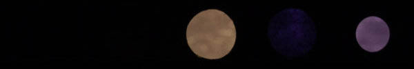
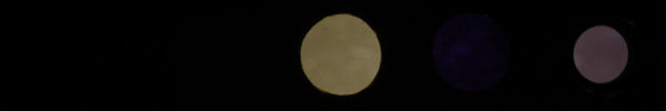
Figure 3. Examples of different light sources imaged through the filter strip. From left to right, the filter peak wavelengths are 325 nm ± 5 nm, 340 nm ± 5 nm, 370 nm ± 7.5 nm, 385 nm ± 5 nm and 400 nm ± 15 nm. The transmission bands of the filters I chose for this use, and a set of test images of different light sources, are shown in Figure 3. A Baader U filter was additionally used on the camera lens to remove the abundant visible and IR radiation generated by the electronic flash. Even in the absence of direct ilumination of the subject by this radiation, enough of it was reflected and diffused by the environment to completely spoil the test picture. Exposure was manually adjusted when shooting and retouched in post-production to produce visually comparable results. The white balance was set in all cases to the same custom value, experimentally found using the camera with unfiltered electronic flash and with a B+W 486 filter mounted on the lens. With this filter, which cuts both UV and IR, the custom white balance gives images that approximately correspond to the original flash white balance of the camera before modification. The unfiltered electronic flash used for this test seems to emit faint levels of radiation at 325 nm and does emit easily detectable levels at 340 nm. The Baader U filter reduces the radiation levels at these wavelengths, and the UV-enabled camera is not very sensitive at wavelengths below 330-340 nm. Recorded radiation levels are higher at 370 nm and longer wavelengths. Thus, this combination of equipment is adequate at 340 nm and higher wavelengths. The two types of UV LEDs used for this tests are rated at 365 nm. In both cases, their actual emission peaks are between 362 and 378 nm. However, their emissions are not identical, as shown by the greener tinge of the 1 W specimen, which likely indicates a significantly shorter peak wavelength than the 3 W specimen. Both LEDs emit small amounts of radiation around 385 nm and none at 325 and 340 nm. The radiation passing through the 400 nm filter must be UV leaking through this filter, since the Baader U filter on the lens eliminates all visible and IR radiation. It might be a good idea to replace the 400 nm filter in the future, since its transmission band (385-415 nm) is a bit too wide, and its tranmission peak (60%) higher than the other filters. The four UV-pass filters have bandwidths of ± 5 to ± 7.5 nm, slightly narrower than typical UV LED emission (nominally ± 10 nm). The 325 nm filter is the least transmissive (12%) and the 385 nm the highest (52%), while the others have a transmission of 25-30%. Combined with the low sensitivity of the camera sensor at 325 nm, which is close to the practical usability limit of normal CMOS sensors, even in the best case the 325 nm filter results in a much dimmer illumination that the others. Unmodified digital cameras should detect no radiation passing through these filters, except the 400 nm one and possibly a faint transmission through the 385 nm one. The way a UV-enabled camera records radiation transmitted by these filters varies according to the white balance set on the camera and, to a lesser extent, on the intrinsic characteristics of the sensor. Figure 3 shows the response of a UV-enabled Panasonic G3 with the filters illuminated by a UV-enabled Bowens 1500 Pro flash unit and using a Kyoei 35 mm f/3.5 type 2 lens known to transmit UV down to 320 nm. Sunlight gives a somewhat different result, but at my location (Sweden), and especially in the winter, sunlight is a rare commodity and I did not attempt to provide a test image with this radiation source. |