MikroTik CCR2004-16G-2S+PC router/firewallMikroTik (sometimes misspelled on the web as Mikrotic, Mikrotics or Microtic) is a company based in Latvia that produces network equipment. Particularly popular among their products are routers and switches ranging from amateur-level naked boards to semi-professional and professional devices ready to install in a network rack at a medium-sized company office or a small- to medium-sized ISP. MikroTik equipment also includes a variety of WiFi access points and antennas for indoors as well as outdoors uses. Technology-wise, MikroTik products are targeted to technically knowledgeable individuals and small to medium companies, and do not include extremely expensive equipment like large chassis-based enterprise switches and large Internet-backbone core routers. Like Cisco routers, MikroTik routers are not meant to be used by beginners, or users expecting to spend just a couple of hours setting up a router for their home network and afterwards leaving the router unattended. If you have no experience with MikroTik routers but know your way around routers and networks, you should expect to invest a few weeks to a couple of months for learning the basics, and practicing with the features likely to be needed in a relatively complex network. If you are like me and feel that learning and experimenting are part of the real fun, you are likely to find out that MikroTik routers are far better value for the money than legacy Cisco routers even in this respect. One undated Cisco versus MikroTik comparison states that Cisco has a 16.01% market share in networking hardware (not specifically routers), versus MikroTik's 2.99%. Multiple Cisco versus MikroTik comparisons are available on the web. They generally agree with regard to the price aspect being more favorable for MikroTik routers. Initial purchase price is lower for MikroTik, with firmware upgrades free and guaranteed for a minimum of 5 years, but in practice likely to last for a far longer time. Documentation and support aspects are more favorable for Cisco, but Cisco's policy of providing free firmware upgrades was rescinded years ago. Firmware updates are now available only to customers paying an (expensive) yearly subscription. On paper, Cisco still provides for free those specific firmware updates that correct security weaknesses, but in practice, based on customers' reactions, the procedure for obtaining these free updates are frustrating and time-consuming, with Cisco support intentionally making the process as difficult as possible. Most owners of second-hand, legacy Cisco equipment are now forced to rely on firmware of unknown reliability found in private FTP archives. Some comparisons also point out that MikroTik routers are better than Cisco routers in packet-filtering facilities. In competent hands, this last advantage may make MikroTik routers more secure and better hardened than Cisco routers. Several Cisco routers are available with an extra security license that provides enhanced security capabilities, albeit at a premium price. These differences make MikroTik routers potentially better suited than Cisco routers as a replacement for dedicated firewall hardware, especially for applications that exclude a paid update/upgrade subscription. For Cisco dedicated firewalls, this paid subscription is remarkably expensive and can exceed the initial purchase of the hardware. Cisco generic routers, on the other hand, are probably less suitable than MikroTik's for use as firewalls. My previous experience with professional and semi-professional network equipment is limited mainly to the Cisco 1900, 2900, 900 and 4300 families of Ethernet routers, plus an assortment of Cisco and D-Link managed switches and one Cisco ASA firewall (see below). Over the years I also used at least two dozen consumer-level routers, access points, switches etc. of makes including Linksys, D-Link, TP-Link, Netgear, Huawei etc. As I see it, the main differences between pro (including semi-pro) and consumer devices are threefold (not including the price differential). There are numerous exceptions to these general rules, but by and large:
A brief experience with a Cisco ASAImmediately before the MikroTik router discussed on this page, I had a chance to get a couple of months' worth of hands-on experience with a Cisco ASA 5525-X, which is a firewall for medium-sized networks. The ASA are a legacy family of firewalls, discontinued by Cisco at different times in the last few years. The throughput of this particular model is 1 Gbps when used as a stateful firewall, and up to 300 Mbps as an IPsec VPN. This sounds good on paper, but the catch is that Cisco Next-gen firewall services require a (quite expensive) yearly subscription. Even with such a subscription, new threat signatures for the ASA will no longer be added after September 2025. Afterwards, protecting a "real" network with an ASA 5500 firewall will quickly become unacceptably risky, and an actively supported firewall (Cisco or otherwise) should be used instead. This is in stark contrast with other types of network appliances, like routers and switches, which often have a useful life of several years once support by Cisco has ended (unless critical security faults are discovered, which are not patched by Cisco). The practical usefulness of a second-hand Cisco ASA firewall in a real-life LAN is therefore limited, at best, to routing and supervision functions in LANs shielded from direct exposure on the Internet behind more effective firewalls. The most reasonable use I can see for a legacy Cisco ASA is, therefore, as a tool for self-learning and training. Configuring an ASA differs in several respects from configuring a Cisco IOS or IOS-NX router, and as far as I know Cisco does not make available VMs for emulating any of the really powerful ASA models (only one or two early models of limited capabilities). Fan noiseUsing an ASA 5525-X in domestic settings is problematic because of the high noise of its four built-in 40 mm fans. Three of these fans are unusually noisy, and their pitch and intensity changes frequently (the lone one in the power supply runs at a constant speed). The shrill, sometimes squeaky sound suddenly turns to a hurricane roar when the fans every few minutes suddenly accelerate to maximum speed, then gradually return to a normal speed over the course of a couple of minutes. Unless you are exceptionally noise-tolerant (or deaf), you will find it difficult to work in the same room with one of these firewalls. If you run this firewall in an apartment or student dorm 24/7, noise-sensitive neighbors will be quick to complain, and with good reason. Silencing an ASA 5525-XMy first attempt to silence the ASA 5525-X was by replacing the three PWM fans on the motherboard with quieter 40 mm Noctua fans. I did not replace the non-PWM fan in the power supply, which is less noisy than the other three. I tried both the 10-mm thick NF-A4x10 PWM and the 20 mm thick NF-A4x20 5V PWM as substitutes for the motherboard fans, but they do not provide enough airflow. The fans end up running at their maximum speed, and within 2-3 minutes the firewall shuts down to avoid permanent thermal damage to the CPU and its voltage regulators. Replacement fans with a maximum PWM speed around 8,000-16,000 RPM work better. I had some success with the Nidec fans from a Cisco ISR 4331, the Arctic S4028-15K, and another equivalent fan type, but these fans run at extremely high speeds and are equipped with ball bearings, and are only slightly quieter than the original fans. As a second attempt, I replaced the three fans in the casing with a 140 mm Noctua Redux fan mounted onto a hole in the top cover of the firewall and oriented to blow air into the case. A side effect of this fan is that its rotation speed is slower than the original fans, and its PWM signal frequency is therefore regarded as insufficient by the circuitry of the 5525-X. The fan LED on the front panel is therefore permanently red. Even running at top speed, this fan was unable to keep up with the required cooling, and the firewall shut itself up within five minutes (even in a 25 °C environment temperature). I could avoid the thermal shutdown only by putting back also the three small fans, which of course is no acceptable solution. Replacing the Redux fan with a Noctua industrial-grade 140 mm PWM fan still caused the ASA to overheat and shut down, albeit after a slightly longer time. An examination of the original low-profile CPU copper heatsink shows that it is attached to the bottom of the casing by four spring-loaded screws passing through holes in the motherboard. The screws are arranged in a square pattern at distances of 75 mm, which complies with the specifications for Intel LGA 115* CPU packages, and screwed into threaded sockets at the bottom of the metal casing. Although it is not possible to mount the bottom plate for a standard LGA 115* heatsink between motherboard and casing (there is no space at all for this plate), the threaded sockets in the casing in principle can be used for fastening a standard CPU heatsink with attached fan. This idea should work in principle, but practice, as often happens, works differently. The thread in one of these sockets broke off while I was trying to fasten the new heatsink to the ASA, and at this point I decided to give up the idea of silencing the ASA, because the problem was getting out of hand, and the possible returns were quite limited in any case. pf.sense and other open-source firewallsAs an alternative to the ASA, I looked into a few free, open-source firewalls. Some, like pf.sense, can run in a customized FreeBSD Linux VM, or directly on PC hardware. The main problem in my case is that I need a firewall throughput of at least 250 Mbps downlink and 100 Mbps uplink to take full advantage of my broadband connection. In turn this means, according to the recommendations on pfsense.org, a 2 GHz PC with at least two server-class 1-Gbps network interfaces. This can easily cost north of 500-600 €. A dedicated PC as a firewall is open to the risk of data corruption in case of blackouts, which in turn causes a potentially long down-time. Some legacy Juniper devices have the same problem. The only Juniper router/firewall I ever tested is a second-hand SRX300 Linux-based device, which I tried some six years ago. This SRX300 did die within weeks because of a failed shutdown (apparently the firmware hung during the power-down process), and I was never able to completely fix its corrupted file system to make it boot again. I don't know whether more recent Juniper devices still have the same problem, because after that experience I kept away from Juniper hardware. At present, I avoid all network equipment that cannot survive blackouts or unplanned shutdowns, because there are plenty of alternatives that can be powered down just by flicking the power switch. Using a Cisco or MikroTik router/firewall is a much simpler, and probably cheaper, proposition than adding a UPS to a Juniper router/firewall. The SRX300 also had unacceptably lengthy boot and shutdown times of several minutes. It is much simpler to use a Cisco or MikroTik hardware device, which is essentially immune to data corruption (unless it is powered off while writing to flash memory, in which case the recovery procedure is usually simple and well-documented). Simply pull the mains plug to power off when it is inconvenient to shut down one of these devices through the CLI. A MikroTik device may record this in the log as an unplanned shutdown caused by a probable power outage, but nothing worse than this. A properly working Cisco 4300 router will power down a few seconds after you flick the power switch off, which seems to mean the switch is not an ordinary power breaker but instead sends a signal to the firmware to start a brief shutdown procedure that ends with a circuit breaker cutting off the power. Why a MikroTik router/firewall
MikroTik has a tradition of producing routers suitable to small-scale deployments of a single or a few
routers that are individually managed. In comparison, Cisco routers are better suited to large-scale
deployments of many routers and other network devices that are tightly integrated together and managed as
a single system. Some of the recent Cisco routers must be managed through a cloud-based
system that requires a yearly subscription. You can purchase lifetime licenses of RouterOS to run on a PC or in the cloud. The price varies with the license tier, with successive tiers providing larger and larger throughput and numbers of clients for specific services (there are also hard, but generally large, limits to routing and switching). The raw throughput of RouterOS pre-installed on MikroTik hardware seems to be limited in practice by the hardware speed, not by the license tier. There are six license tiers, with the most powerful MikroTik devices coming with tier 5 or 6 lifetime licenses pre-installed and pre-activated at the factory. Software licenses to run on a PC or in the cloud come instead with a short free grace period and must be activated a shortly after installation. Low-tier licenses are cheaper and especially useful in a home network lab, but may also be sufficient for a simple home network. Minimum-throughput (1 Mbps) licenses meant to be installed in the cloud are free, and only require a free registration with MikroTik. All paid licenses come with a 60 days free evaluation period. Currently, 45 US$ buys you a perpetual 1 Gbps license that can be upgraded for free to future RouterOS versions. If you are on a tight budget but own a reasonably powerful PC (e.g. a gaming machine), this is an excellent way to build a low-cost virtual lab running on a home PC, fully suitable for learning RouterOS. On most PCs you can probably run two or three simultaneous virtual instances of RouterOS, so you can build a reasonably complex virtual network. Compare this to the typical home labs used for learning Cisco IOS, which may include two or three legacy routers and as many switches, sounding like a jet plane ramping up for takeoff, using in total a good kW of electricity, and warming up the room accordingly. Most of the semi-pro and pro MikroTik routers are equipped with active cooling by internal fans and designed to be rack-mounted in a server room. Quite a few models, however, are equipped with passive cooling. This includes mostly low-end models, but also a few advanced models like the one discussed here. In addition to routers, MikroTik sells several types of managed switches (both Ethernet and SFP/SFP+) running SwitchOS, which appears to be a modified and scaled-down version of RouterOS. There are (or were in the recent past) some known incompatibilities between MikroTik switches and routers, e.g. at least one switch model equipped with SFP+ cages being unable to connect at 10 G to a MikroTik router also equipped with SFP+ cages. SwitchOS also seems to be updated less frequently than RouterOS. Some of the smaller MikroTik devices come by default with a dual-boot system that allows them to boot to either RouterOS or SwitchOS. MikroTik also sells an ample range of mobile and WiFi devices, especially several models of medium- and long-haul WiFi bridges for outdoors installation. I have no hands-on experience with these types of MikroTik products. 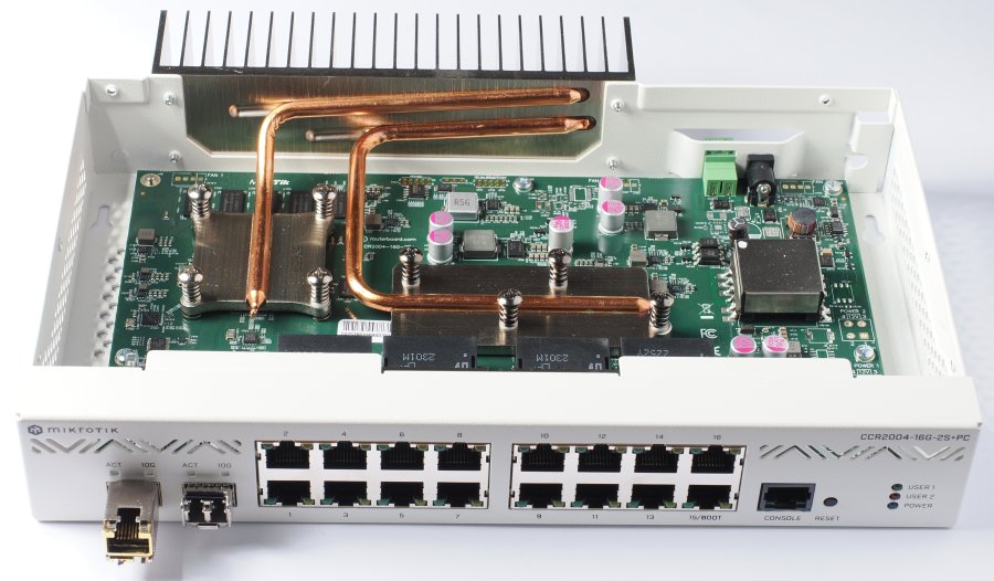
The MikroTik CCR2004 series consists of dedicated hardware routers running MikroTik's RouterOS operating system on a 4-core CPU. RouterOS is based on Linux, but heavily customized, and normally you will not directly access its underlying Linux services. CCR stands for Core Cloud Router, which indicates that these routers are more powerful and versatile than typical edge routers for home and small-business networks. This series is not meant to be used only as an edge router, and is not pre-loaded at the factory with a full configuration typical of an edge router. However, RouterOS does have a wizard-like facility that helps to quickly create a simple configuration usable as a starting point in a role as edge router. Unlike Cisco and other manufacturers, MikroTik does not provide a customized version of firmware for each hardware router model or series, but only eight versions of RouterOS for the different supported CPU platform (including the 32/64 bit variations of the same platform). This has the practical consequence that certain configuration procedures (e.g. offloading of functions from the CPU to dedicated switch hardware) differ, depending on the type of hardware used in different models, in spite of these models using the same CPU platform and code base. The CCR2004-16G-2S+PC was introduced in the MikroTik newsletter #105 on April 7, 2022, and is therefore slightly over one year old at the time of writing. Breaking down the model denomination:
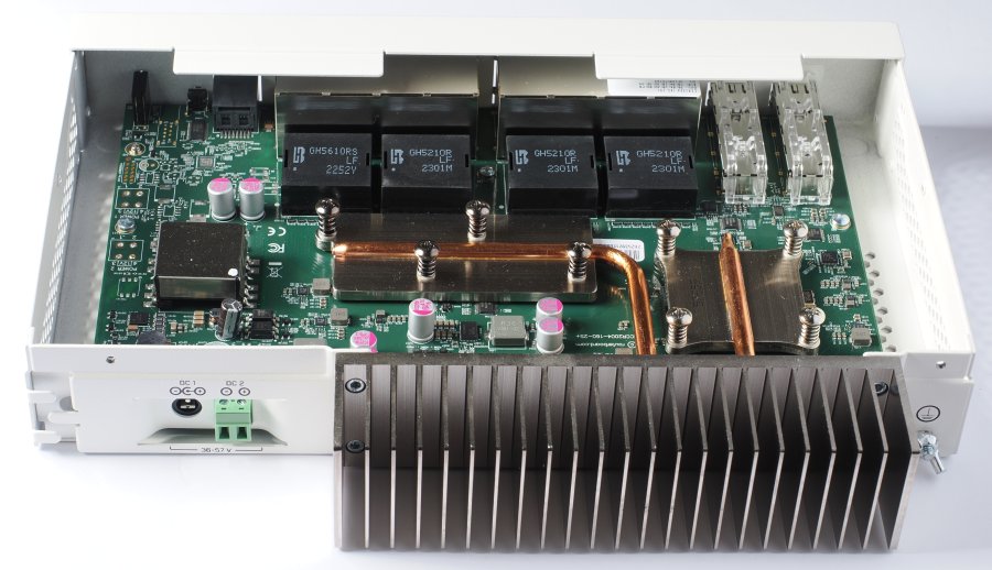
More details about MikroTik's CCR-series model denominations are available here. As seen in Figure 2, the CPU (under the square metal plate bolted to the motherboard with four spring-loaded screws) is connected to the rear heatsink by a heat pipe. The bolted rectangular plate, connected to the heatsink by a second heat pipe, covers two dedicated LSIs, each containing the hardware functionality for handling eight 1-Gbps Ethernet interfaces. This means that, within each group of 8 contiguous Gigabit interfaces, much of the L2 functionality can be offloaded from the CPU and performed in specialized hardware. This includes, for example, the bridging functionality required to operate a group of interfaces as an L2 switch. Therefore, whenever compatible with the role of the router, for maximum performance with minimum CPU load each of the two groups of 8 Gigabit interfaces should be configured as a bridge. Each of the switch chips has a hardware data channel to the CPU. Each bridge can be given L3 attributes, and perform like a routed virtual interface. Each of the 1-Gbps interfaces (in addition to the SFP+ interfaces), if not bridged can be individually configured as a fully routed interface. In the default configuration, the ether1 interface is used as the WAN interface, but this is in no way obligatory. SFP+ cages, transceivers, and fiberThe two SFP+ cages support transceivers capable of 10, 5, 2.5, 1.25 and 1 Gbps data speeds. Each cage is connected to the CPU by a hardware data channel. If operated as part of a bridge, hardware offloading of the bridge functionality is not possible for these cages. As a result, it makes better sense to use each SFP+ cage as a 10-Gigabit up-or downlink with its own IP address and L3 router functionality (with additional L2 functionality if required, e.g. VLANs). The SFP+ cages are not internally equipped with heatsinks. Users have reported that 10 G RJ45 Ethernet transceivers in these cages can get very hot. I tested such transceivers but do not use them on a regular basis, because I prefer to proactively avoid the risk of overheating inherent in these transceivers. Among 10 G fiber transceivers, MikroTik only offers a singlemode simplex set of two transceivers (a simplex fiber requires two transceivers working at complementary wavelengths, not two identical transceivers as recommended for duplex fiber) and a multimode duplex model. The latter (MikroTik S+85DLC03D), is rated at 850 nm and up to 300 m. Like the SFP+ cages of the router, these transceivers support 10, 5, 2.5, 1.25 and 1 G. This partly explains the significantly higher price of these transceivers, compared to third-party transceivers operating only at 10 G. I had the following transceivers available for this test:
I repeated the test with the Qiniyek fiber transceivers after adding inline singlemode attenuators on both incoming and outgoing fibers at one transceiver. Data traffic was errorless with 5 dB attenuators, but the transceivers refused to acknowledge the connection with 10 dB attenuators. Removing the attenuators from the first transceiver and connecting two similar 5 dB attenuators to the second transceiver resulted in an unreliable connection that reset itself every few seconds. The 5 dB attenuators used for this test are individually calibrated at the factory, and the specimens in my possession actually vary between 5.01 and 5.26 dB at 1,310 nm, or ±2.38%. It is not clear to me why the result was different in the two cases with 5dB attenuators. The only actual differences in the experimental setup are:
These transceivers only operate at 10 G, so they cannot switch to a lower speed when they detect a drop in line quality. According to OS2 specifications, this fiber type has a maximum attenuation of 0.4 dB/km, so the maximum attenuation of a 10 km OS2 fiber link is 4 dB, plus the maximum 0.2 dB insertion loss specified by the maker of this particular fiber. The fact that these transceivers may work unreliably with 5 dB attenuation suggests that their performance is marginal at this amount of attenuation, and small individual variations will determine whether the link will actually work when the actual fiber length exceeds the maximum length specified by the manufacturer by only 10% to 20%. In conclusion, I tried all the SFP and SFP+ transceiver types in my possession, and they all worked in this router when coupled to short lengths (up to 20 m) of the appropriate fiber type. Among these transceivers, all fiber types remain cooler than the 1G RJ45 transceivers. This confirms my experience so far with both general types of transceivers. Estimates of power consumption of RJ45 vs. fiber Ethernet vary among Internet sources, with RJ45 Ethernet said to use between 3.5 and 7 times more energy than fiber. An obvious disadvantage of fiber vs. RJ45 networks is that optical fiber is difficult to splice reliably without expensive equipment. Cold splicing is possible in emergency situations, and should only be regarded as a temporary fix, because the droplet of fluid bridging the optical gap between the spliced fiber ends may eventually leak out, become contaminated, and/or dry up. The rather wide variety of fiber types and thickness makes it necessary to keep available a relatively large assortment of parts, to ensure you will have the proper parts available when the need to make a cold joint arises. Even properly made cold joints remain vulnerable to humidity, flooding, extreme temperature changes, contamination, and mechanical loads. Professional fiber installers use a fusion splicer to permanently join two fiber ends. This type of joint can be regarded as permanent, and is the best possible joint one can perform in the field. Fusion splicers are largely automated but quite expensive, and start at around 1,000 €. The splices must then be tested with a variety of (also expensive) test devices to verify their integrity and make sure the attenuation and backscatter of the joints are within specifications. For long-lasting connections, you should only use ready-made fiber patch cords complete of factory-installed, non-removable connectors. LC connectors are today the rule for SFP and SFP+ transceivers. If necessary, two patch cords with molded LC connectors can be joined together by an LC-to-LC double socket (an LC duplex connector prevents accidentally cross-connecting the two fibers of a duplex pair). In reasonably clean and dry indoors environments, this type of joint will be more durable and reliable than a hand-made splice. Among fiber transceivers, multimode ones tend to be cheaper than singlemode. Single-speed transceivers are likewise cheaper than multi-speed transceivers. Optical transceivers equipped with longer-wavelength IR lasers tend to be more expensive. Multimode patch cords are slightly cheaper than singlemode, available from a larger number of retailers, and sold in a larger range of short lengths than singlemode fiber. Singlemode fiber and transceivers are usually the only available choice for lengths exceeding 100-300 m. SFP and SFP+ transceivers are hot-swappable and can be inserted and removed without powering down the network equipment. Typically, the network equipment detects within seconds when a transceiver is plugged in or removed, and when a data link with a transceiver at the opposite end of the physical media is established or interrupted. However, dual-media interfaces equipped with both an RJ45 and an SFP(+) port may need to be manually configured to set which media (RJ45 cable or SFP transceiver) is preferred. Usually, dual-media interfaces automatically failover from one type of media to the other when the preferred media is no longer functioning. Multimode patch cords tend to have a thicker and stiffer plastic jacket, which may be more resistant to damage but also displays a higher tendency to escape from the open D-rings often used for cable management. Both types of fiber, in any case, must never be sharply bent, tied with nylon cable ties or a plastic spiral sleeve, nor bundled together with RJ45 Ethernet cables or power lines. Loosely tying with a soft, 20 mm wide double-sided velcro tape is the method generally preferred for data fiber. Excess lengths should be coiled into a roll with a diameter not smaller than about 15 cm fastened with soft velcro ties and hung from rack cable supports, rather than left hanging loose. Fiber patch cords should never be left running unprotected on a floor. Whenever a patch cord is not plugged into a transceiver, the ends of the patch cords must be protected with the appropriate plastic or silicone rubber plugs. The optical ports of the transceivers must also be protected with the appropriate plugs when not is use. Armored fiber patch cables are surrounded by a spirally wound steel ribbon and an external plastic jacket. They are far less delicate than ordinary fiber patch cables, and some types are certified for outdoors use. Both simplex and duplex types are available, but typically they are simplex singlemode and available in lengths starting at 5-10 m. Armored fiber cables are much stiffer, and must be coiled to a higher coil diameter (30-40 cm is a reasonable diameter). Armored patch cords should also be jacketless for a few cm next to the connectors, in order to enhance their flexibility at these positions and reduce the mechanical stresses on the connectors (LC connectors in particular can be vulnerable to mechanical stress, because of their lower cross-section). For long-haul installations, mainly jacketless bulk fiber is used, typically sold in 1 km and longer spools and meant to be inserted into hollow conduits in the field by specialized air-blowing machines and fusion-spliced. Photonic-crystal hollow-core fiber displays significantly lower transmission losses than traditional singlemode fiber and looks promising as the next-generation medium for long-haul fiber installations, but requires new equipment for fusion splicing in the field. In most countries, damage to buried long-haul data fiber by careless digging is nowadays a daily occurrence, and perhaps the most frequent cause of local Internet outages. For a summary of the most common data fiber types, specifications and industry conventions, see e.g. singlemode and multimode fiber on Wikipedia. Panel LEDsWhile most of the LEDs on the front panel require no explanation, the meaning of the USER1 and USER2 LEDs is far from self-explanatory. By default, they do nothing. Their function can be configured e.g. with WinBox (under System, LEDs). For example, I set USER1 and USER2 to blink when the software-defined bridges I use to group the WAN and LAN interfaces, respectively, are transmitting data (in this way, I get an idea of the direction the routed data is flowing between WAN and LAN). The color of the LEDs, however, cannot be configured. The function of the four LEDs above the SFP+ cages can also be reconfigured in the same way (although I much prefer to keep their default functions). PowerThis model uses a small external 48 VDC 0.7 A (35 W peak) wall-wart power supply, which further lessens the cooling requirements of the electronics within the metal casing. Several unused soldering pads along the right side of the motherboard suggest that the same PC board is used also in CCR2004 models equipped with dual internal power supplies. These models have internal heatsinks on the CPU and switch controllers, and require active cooling by multiple 40 mm fans. They are fine to use in a server room, but given my negative experience with a Cisco ASA firewall that turned out to be extremely difficult to silence (see above), this time I decided to get a completely silent device ready to use out-of-the-box. This silent version, incidentally, costs exactly the same as the fan-cooled version with dual internal power supplies. The shielded square box on the left side of the the motherboard in Figure 2 seems to be a step-down voltage converter. This module is missing on the motherboard of actively cooled models (but its soldering pads are present). This indicates that the motherboard used in all CCR2004 models was designed from the start to have multiple power options, although the PC model was released some time after the actively cooled model with internal power supplies. The CCR2004-16G-2S+PC has a second connector for another power supply (not included with the router), this one connected to screw terminals on the rear panel. Can you use this connector simultaneously with the provided power supply, and achieve redundant power supplies? The documentation is of no help in this respect. It mentions redundant internal power supplies, which means that this sentence was copy-pasted from the documentation of the actively cooled model, but never modified as required to apply to the passively cooled model. Perhaps this is due to the passively cooled model being relatively recent, but the quality of technical documentation for a professional network device should be better than this. A threaded bolt protruding from the rear of the casing near the heatsink is used to attach a ground cable, fastened with a wingnut. The wingnut is a nice touch, because it can be tightened or loosened by hand, without requiring tools. Typically, the ground cable is not visible from the front of the rack, so while removing the device from a rack cabinet it is often a surprise to discover that it is still connected to the rack by a ground cable, and reaching for the right screwdriver with one hand while holding the device still tethered to the rack in the other hand is not always easy. Rack earsThe router comes with rack ears for a standard 19" rack. One ear is very short, the other over 19 cm long and made from quite thin metal sheet. It is stamped with two longitudinal ribs to make it stiffer, but it is still much too flexible nonetheless. It bends inwards by over one cm whenever I plug an Ethernet cable into a socket on the front panel, and I am quite sure it will not keep its shape after a year of one-handed plugging and unplugging. This is a weak point in the mechanical design. The device will last longer if you prevent it from moving back and forth by holding the casing with the other hand, but this is not what I expect from a professional device. All my Cisco and D-link devices, including a few Linksys-designed semi-pro models, have much stiffer rack ears. Also in this case, the description and pictures in the online documentation show the rack ears for the actively cooled model, not those actually provided with this router model. The metal casing seems to be made from stamped metal sheet similar to the rack ears, but does not feel overly flexible. In practice, however, the casing of this router is still likely to last a lifetime, even though it does not have the "sturdy like a tank" feel of Cisco devices from 20-30 years ago. After all, not many of us take our routers on an offroad trip in the desert or a parasailing excursion in the mountains. Wall mountingTwo keyhole-shaped holes in the bottom of the casing can be used to hang the router on a wall. They only allow a router orientation with the front panel lowermost. The holes are placed outside the internal area occupied by the motherboard, so it is not possible to short out the electronics by using hanging screws that protrude a little too much from the wall. Rubber feetFour small, thin adhesive rubber feet are included among the accessories. They fit into slight depressions of the bottom of the casing, and may be useful if you intend to just place the router on a tabletop or shelf. You may want not to use the feet if you plan to mount the router in a rack, because the height of the casing (43.7 mm) is quite exactly the same as the standard height of a 1U rack slot. Color and styleThe MikroTik CCR2004 series is housed in white metal casings, with no plastic fascia. The whole casing, included the bottom and the interior, is spray-painted in the same color. The same casing style is also used by several current and recent MikroTik switches. This is a break from the typical black casing of perhaps 95% of network equipment, and from their largely plastic front panels. In the past, MikroTik has used a variety of casing styles, ranging from cheap-looking plastic enclosures for small switches, to typical all-black casings, to a few routers and firewalls in fiery red metal casings. A few MikroTik routers are housed in 1/2 U high casings that consist mostly of a single large heatsink for passive cooling. Up to four such devices can be mounted together in a single 1U rack slot. We should give credit to MikroTik for the creativity of some of these casings. In comparison, the CCR2004 series is quite conservative, except for a distinctive zig-zag pattern of thin ventilation slits on the front panel, which seems more ornamental than functional. The hexagonal ventilation mesh on the rest of the casing allows a good ventilation of the internals. Passive cooling in practiceSince the metal casing has ventilation grids on its top, bottom and both sides (plus minimal ventilation slits on the front panel), an adequate amount of cooling requires that this router, when rack-mounted, has an empty rack slot immediately above. It may help having an empty slot also under the casing. This is not as bad as it may sound, as these empty slots can still be used for e.g. patch panels and power strips. In addition, the rear panel carries a large heatsink quite similar to the one of several Cisco small-business switches. This means that the router cannot be mounted in a hermetically closed rack enclosure. In my case, to help the passive cooling I mounted a 12 cm low-noise Noctua fan on a 3U rear rack panel blowing directly onto the heatsink, and set it to run continuously at a low speed with an adjustable Noctua NA-FC1 fan controller. This makes the fan inaudible even at close range. I found that even this slow air current is quite effective in keeping the heatsink barely warmer than ambient temperature, and the top of the casing completely cool to the touch. In my present setup, the router is mounted in the center slot of a 3U mini-rack cabinet with open sides and no doors. A patch panel is mounted at the front of the lowermost slot, and a power strip at the rear of the same slot. A 12 cm fan is mounted on a 3U fan panel mounted on rack extenders, recessed about 15 cm from the rear of the rack. The top and bottom of this rack enclosure is a stamped, non-ventilated steel plate, convenient to support the weight of a laser printer. In this way, the rack enclosure does not waste any footprint space, which is at premium in my office/lab. The rack slot immediately above the router is necessary to help with passive cooling, but it is possible to switch the positions of the router and patch panel and get a usable, empty 1U space at the top of the enclosure. A 1-cm gap between the top of the uppermost 1U slot and the steel cover of the cabinet, with the help of the fan, also makes it potentially feasible to use this slot for a passively cooled device. The motherboard has connector pads for two fans. Adding fans is not as simple as soldering their cables to these pads and modifying the case, because the motherboard also lacks the components necessary for fan speed control. SpecificationsThe CCR2004-16G-2S+PC uses a 4-core 1.2 GHz ARM64 CPU, two 88E6191X switch chips, and is equipped with non-expandable 4 GB RAM and just 128 MB of flash. The Marvell information on the 88E6191X says that it is a single-chip device supporting eight Gb Ethernet ports and three additional interfaces up to 10 Gbps each. Therefore, four of the 10 Gbps channels of these chips are left unused, and the router could in theory have supported four additional SFP+ cages. Keep a note of the switch chip type used in your MikroTik router well in sight when configuring VLANs on the router, because the optimal VLAN configuration method (among other things) changes according to the switch chip type. The router configuration is stored in a proprietary binary format, not as a text file (unlike e.g. in Cisco routers). Therefore, a simple configuration takes up only a few tens of KB, not multiple MB. If your current or planned configuration threatens to become overly large, you can download older backup files to a PC and store them offline, rather than leaving them on the router. In the case of an extremely large configuration you may wish to go over the configuration and reduce the length of comments to a minimum. Most settings can contain a freetext comment, which may take up a significant amount of memory. These comments are a dedicated field of each setting, and must not be confused with scripting comments that begin with # and are not stored in the configuration. More specifications and capabilities of the CCR2004-16G-2S+PC are listed here. Unlike the majority of comparable routers, the CCR2004-16G-2S+PC has no USB ports. There are solder pads on the motherboard for one USB socket on the front panel, between the LEDs and the reset button, but no USB port in the current CCR2004-series models. Some pictures of CCR2004 routers I found on the web do show a USB port on their front panel, so it is likely that prototypes, and possibly an early release series, did have such a port. A USB port could be a way to supplement the built-in flash memory, which is unusually small for a router of this performance class. On the other hand, according to my experience with the USB ports of Cisco routers, there are frequent problems with incompatible USB sticks, as well as limitations to USB memory size and type of file system, so perhaps there are good reasons to get rid of this potential source of problems, besides saving perhaps 5 € on hardware manufacturing costs and eliminating the need to maintain and debug the USB-related functionality in RouterOS. The motherboard has no user-upgradeable components. If you need a router with upgradeable internal storage, some of the larger CCR models can be equipped with internal M.2 SSDs. ConfigurationThe basic configuration of CCR2004-series routers is discussed here. SummaryThe MikroTik CCR2004-16G-2S+PC is a powerful Ethernet router equipped with sixteen 1G RJ45 Ethernet interfaces and two SFP+ cages capable of running at up to 10 G. It is not restricted to a role as edge router, and all 18 interfaces are fully routable. All RJ45 Ethernet ports are additionally supported by L2 and L3 hardware offloading that free up substantial amounts of CPU processing. 10 G routed traffic via SFP+ transceivers is possible in reasonably complex network architectures. MikroTik offers free and acceptably timely security updates to RouterOS for a minimum of 5 years, and in practice for lifetime unless prevented by hardware limitations. This router also provides reasonably sophisticated firewall capabilities, but MikroTik does not provide a subscription service to keep the firewall updated against new threats. Price is substantially lower than for Cisco routers of comparable capabilities. Possible drawbacks are that RouterOS differs from Cisco IOS, so a specific knowledge of the latter is not directly transferable to MikroTik routers, and the installed base of MikroTik routers is smaller than Cisco's. Consequently, published information on RouterOS (by both MikroTik and third-parties) is smaller than Cisco's. Nonetheless, all the information necessary for self-learning is available, and a sufficient number of paid courses and MikroTik professional certifications is available. |