Depth of field and resolution in close-up, macro photography and photomacrographyNote: I wrote this page a few years ago and did not update its contents since. While the discussion of DoF on this page is correct, the calculations and the given DoF formula can be simplified and slightly corrected. There is a more updated, extensive and reliable coverage of DoF in my book "Digital photography for science". The Excel spreadsheed accompanying this book contains a set of DoF dynamic tables and is freely downloadable from the above link. Depth of field (DOF) is of special concern in close-up, macro photography and photomacrography. As discussed here, all else being the same, DOF decreases as magnification increases. As a consequence, pictures taken at high magnification suffer from a shallow DOF. This tell-tale DOF allows a viewer, for instance, to immediately tell the difference between a landscape and a close-up of a landscape model. In macro and photomacrography, DOF may be so shallow that only a small part of the subject is in focus. A common recommendation in macro photography is to stop down the diaphragm in order to achieve the maximum DOF. This is essentially correct, but by blindly following this advice you may also achieve a visibly lower resolution in your pictures. Circle of confusionThe circle of confusion is the size of the largest unsharp blob that can be perceived as sharp when looking at a photograph. Its definition is somewhat subjective, but in the case of digital photography with a 16 by 24 mm sensor it is usually 20 μm in diameter (on the sensor, not on a printed picture). Considering that pixels on a Nikon D200 sensor have a pitch (= distance between centers of adjacent photo sites along orthogonal directions) of approximately 6.2μm, the circle of confusion for this camera is roughly 3 pixels across. On a digital sensor, 3 pixels are also the minimum distance at which two points can be rendered as separate. In addition, the actual resolution of a digital sensor is reduced by its anti-aliasing mask, which spreads light from a point-source to an area with a diameter of 2-3 pixels or more. Therefore, it is reasonable to say that an area with a diameter of 3 pixels represents the practical resolution limit for this camera. Other modern cameras and sensors do differ, but not by very much (keep in mind that doubling the number of photo sites of a sensor only increases its theoretical linear resolution by roughly 1.3 times, so things are not going to change much until we get to 30 megapixels or more, which could be outside the useful range of resolution for general-purpose cameras). The DOF zone is delimited by the distances at which out-of-focus points are rendered as blobs the size of the circle of confusion. Where the blobs become larger, the picture is perceived as out of focus and blurry. Of course, this is based on the perception of circles of confusion of gradually increasing diameters, so there is no clear borderline between in-focus and out-of-focus distances, and some subjective judgement is involved as well. Note that most macro lenses display the nominal aperture (i.e., lens diameter / focal length), but a few display instead the effective aperture (i.e., the nominal aperture multiplied by the exposure factor, which is 2 stops at a magnification of 1x). Effective aperture in macro photography is computed as E = N (M + 1) where E is the effective aperture, N the nominal aperture and M the magnification. However, the above formula is only an approximation. The pupil ratio is measured in practice as the apparent diameter of the diaphragm image as seen from the rear of the lens, divided by the apparent diameter as seen from the front (note that the apparent diameter is not the same as the actual diameter of the aperture, which of course is the same when measured from the back or front). In lenses of "medium" focal lengths and simple optical schemes, the pupil ratio is often close to 1, and in this case the above formula is precise enough. However, lenses with significantly asymmetric optical schemes have a pupil ratio than can approach 2 (e.g. wideangles, as well as modern lenses designed for photomacrography), or 0.5 (especially telephoto lenses). This skews the result of the above formula by up to one stop either way, which is too much to ignore. In these conditions, effective aperture is more precisely given by E = N (M / P + 1) DOF in macro photography is often computed as 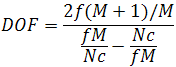 where f is the focal length and c the circle of confusion. Based on the above, the following DOF table can be calculated. DOF is expressed as the total depth of field, i.e., the sum of the depth of field in front of and behind the plane of focus. Table 1 displays the nominal aperture in the top row of headers, and the corresponding effective aperture in the following rows. For now, let's ignore the areas framed in pink and red in the table (they are explained below). Also, the following table ignores pupil ratio. 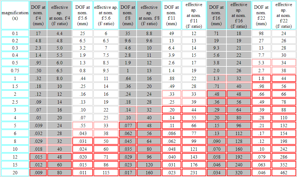
So far, all is well, and by extending the above table ad infinitum it would appear that any DOF can be achieved, as long as we agree to pay its price in terms of longer exposure. After all, we do know that we can close the aperture of a lens by one stop and expose for twice the time, and still get the same result (except, of course, for a higher DOF). This is known as reciprocity rule. Incidentally, Table 1 is computed for a lens of 50 mm focal length. While the focal length does have have an effect on DOF at very low magnifications, its effect steadily decreases as magnification increases, and DOF becomes the same, regardless of focal length, at 1x. Table 2 shows the DOF at f/16 and a magnification of 0.1x for lenses of different focal lengths. At this magnification, still far from the macro range, the differences in DOF are already minimal, and can safely be ignored for most purposes.
Table 2. DOF as a function of focal length (computed at nominal f/16 and 0.1x). Unfortunately, the devil is in the details, and DOF is no exception. Most photographers who have used film still remember a phenomenon called reciprocity failure. Simply put, it means that, outside a certain interval of exposure times, the sensitivity of film decreases as exposure time increases. Outside this interval, exposure times must be much more than doubled for closing down by each stop. Digital camera sensors behave in a partly similar way. With long exposures, noise overwhelms the signal. With both film and sensors, lowering the temperature decreases noise, but a liquid nitrogen-cooled digital camera is not a practical approach for most photographers. Increasing illumination is a way to compensate for a narrow aperture, but also this method is inconvenient. A short flash of illumination 1,000 times stronger than sunlight, for instance, is likely to vaporize a small subject and permanently damage the photographer's sight. Even if you did follow these approaches, anyway, the devil has yet another trick in store for you. DiffractionQuantum theory says that light is both particles and waves. In our case, this means that light interacts with objects in subtler ways than just following a straight line, or being refracted and reflected. In addition to the above behaviour, light rays that pass very close to object edges are bent. This is one of the aspects of diffraction. In the case of a camera lens, diffraction affects light passing close to the edge of optical elements and to the edge of the diaphragm. The latter is especially important when the diaphragm is stopped down. The open area of the diaphragm is proportional to the square of the diaphragm's diameter, while the perimeter of the diaphragm is proportional to its diameter. This means that, when the diaphragm is stopped down, its aperture area decreases more rapidly than its perimeter. In turn, the above means that the portion of light that passes near the edge of the diaphragm and is diffracted grows proportionally. This is usually simplified by saying that the effects of diffraction increase, when we stop down the diaphragm. Any light that does not travel in a straight line ends up on a "wrong" area of the camera sensor or film. Diffracted light does not spread uniformly, but produces an image with a bright center spot and alternating dark and light rings surrounding it. The end result of diffraction is a loss of resolution and short-range contrast. The physicist George Biddell Airy quantified this with the formula: 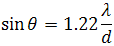 where λ is the wavelength, d is the aperture diameter and θ the angle of minimum separation for two points to be imaged as separate. This formula applies at a significant distance from the aperture (which is the case in camera lenses). Since θ is small, and we are primarily concerned with the f-stop aperture, the formula can be written:  where x is the minimum separation of two points on the film/sensor, and f/d is the f-stop aperture. The diameter of the bright center spot of the diffraction pattern up to the middle of the surrounding dark ring is called the Airy disk. Remember that it has nothing to do with air, and that it should be capitalized. The above formula allows us to calculate the diameter of the Airy disk for the apertures of Table 1. For instance, if we take λ = 420 nm for blue light and an f/32 aperture, the Airy disk is 16.4 μm, or still less than the circle of confusion. In other words, diffraction has no visible effect in this case. If we take λ = 650 nm for red light at the same aperture, the Airy disk is 25.4 μm, or already slightly affecting the resolution. The fact that really makes things bad for us is that the effective aperture is the one that counts, both in terms of exposure time and diffraction. Therefore, a large portion of the effective apertures shown in Table 1 produces fuzzy pictures to some extent. In Table 1, I framed the borderline values (slightly affected by diffraction) in pink, and those definitely affected in red. If you want to achieve maximum resolution, stay away from these areas. The same data shown in Table 1 can be summarized as follows, for your convenience (Table 3). For each magnification, use a wider aperture than the nominal one shown below to avoid diffraction as much as possible, and exceed the suggested aperture values only at your risk (i.e., when a higher DOF is worth a visible loss of resolution). Keep in mind that the shown values are computed from theoretical considerations, but in practice, for the best possible resolution, and depending on the performance of the lens you are using, probably you should stay at least 1-2 stops below the shown apertures.
Table 3. Nominal aperture at which diffraction affects the visible resolution, as a function of magnification (computed for the sensor of a Nikon D200). As a last note, although there is no known way of bypassing the laws of quantum mechanics, we do have a couple of ways to beat the devil, at least with stationary subjects, and achieve a practically unlimited depth of field in photomacrography (besides using a scanning electron microscope or an atomic force microscope). You are welcome to check up the entry on focus stacking on Wikipedia, and make a web search on light scanning photomacrography. |